温度传感器
支持的芯片[ RTL8720E ][ RTL8710E ][ RTL8726E ][ RTL8713E ][ RTL8730E ][ RTL8721F ]
简介
芯片的温度传感器用于监测芯片内部温度,并提供低温预警、高温预警和过温保护。
当温度超过限制的高温阈值时,将向 CPU 发送中断,CPU 可以降低频率。
当温度超过限制的低温阈值时,将向 CPU 发送中断,CPU 可以提高频率。
当温度超过限制的过温保护阈值时,硬件将自动断电以进行过温保护。
特性
无须校准
测量范围:-40°C ~ 125°C
偏差:±1.5°C(典型值),±5°C(最差情况)
分辨率:0.0125°C
时钟:2MHz
19 位传感器温度值:1 个符号位,8 个整数位,和 10 个小数位
提供低温预警、高温预警和过温保护
为温度使能位和过温保护使能位提供访问保护
框图
温度传感器框图如下图所示:

温度传感器模块包括以下子模块:
偏置电路
为双极性核心产生偏置电流。
双极性核心
产生与温度相关的电压 ΔV_BE 和 V_BE。
∑-∆ ADC
包含一个 ∑-∆ 调制器和一个抽取滤波器。
输出与温度相关的数字值。
控制器
控制和管理中断。
控制低温预警、高温预警和过温保护。
寄存器
包含配置寄存器、结果寄存器和中断寄存器。
提供与软件的接口。
允许直接从寄存器读取测量温度。
双极性核心
为了产生数字温度读数,必须进行比率测量:将与温度相关的信号与参考信号进行比较。
虽然几乎每个器件都具有与温度相关的特性,但使用两个二极管连接的衬底 PNP 晶体管来产生两个电压:一个具有负温度系数(V_BE),另一个具有正温度系数(ΔV_BE)。它们可用于产生与绝对温度精确成正比的电压(PTAT)以及与温度无关的带隙基准电压。
衬底 PNP 晶体管的框图如下图所示:

温度、V_BE 和 ΔV_BE 之间的关系如下图所示:
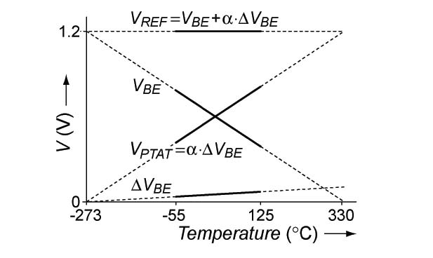
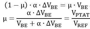
μ = (α * ΔV_BE) / (V_BE + α * ΔV_BE) = V_PTAT / V_REF
V_PTAT = α * ΔV_BE,与绝对温度成正比。
V_REF = V_BE + α * ΔV_BE,是一个传统的带隙基准电压(约 1.2V),具有零温度系数。
μ 与温度成正比;应合理选择 α 以达到目标 V_REF。
∑-∆ ADC
∑-∆ ADC 包含一个 ∑-∆ 调制器和一个抽取滤波器。V_BE 和 ΔV_BE 输入到 ∑-∆ 调制器,该调制器产生一个比特流 bs,其平均值 μ 等于 α * ΔV_BE 与 V_REF 的比值。抽取滤波器用于滤除来自比特流 bs 的量化噪声,并执行所需的缩放以获得 ADC 输出 Dout。
∑-∆ 调制器的框图如下图所示:
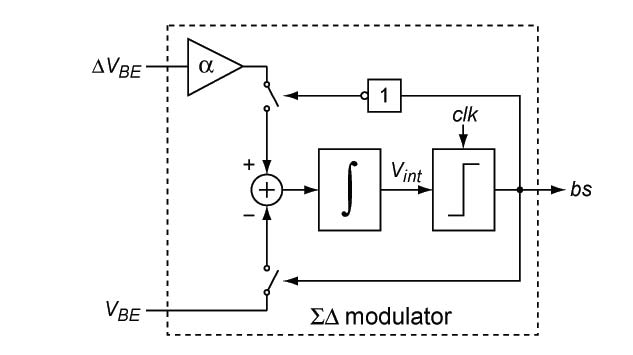
∑-∆ 调制器由环路滤波器和时钟比较器组成。为简单起见,仅显示了一阶环路滤波器。在实际调制器中,使用的是二阶滤波器。每个时钟周期,比较器根据环路滤波器的输出 Vint 的极性产生比特流 bs 的一位。反馈被安排为使积分器的输出趋近于零。
如果在给定的时钟周期中比特流为零,则对 α * ΔV_BE 进行积分;如果比特流为一,则对 -V_BE 进行积分。这可以表示如下:
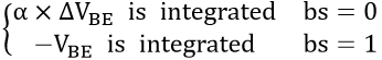
由于调制器中的反馈,积分器的平均输入为零。换句话说,由 α * ΔV_BE 添加的电荷与由 -V_BE 移除的电荷相平衡。
因此 ∑-∆ 调制器实现了 μ 的量化。
功能描述
操作流程
温度传感器操作流程如下图所示:

温度传感器的工作流程主要分为初始化阶段与连续监测阶段。系统通过对传感器输出温度( TM_OUT )与预设的三个阈值进行持续比较,采取不同的软硬件保护机制,具体流程如下:
初始化阶段
系统启动后首先进入初始化流程。在此阶段,系统按顺序执行以下操作:
配置模数转换器(ADC)的相关参数。
设定各级温度阈值,并使能阈值比较功能。其中,温度阈值为摄氏温度对应的二进制补码数值(1 个符号位 + 8 个整数位),如 125°C 对应的阈值为 0x7D,-40°C 对应的阈值为 0x1D8。
使能温度传感器模块(量产版本默认开启此功能)。
开启中断使能,为后续的温度警告与保护动作做准备。
连续监测阶段
初始化完成后,系统进入连续的温度阈值判定循环,按照优先级依次进行以下三种状态的检测:
过温保护判定(TM_OUT >= TM_HIGH_PT_THR)
系统首先判断传感器输出温度( TM_OUT )是否大于或等于过温保护阈值( TM_HIGH_PT_THR )。
若满足条件:触发热复位(Thermal reset)。
硬件行为:硬件自动将
TM_TIMER中的定时周期值加载至 AON 定时器中,定时器单位为 0.65s。执行热复位后启动 AON 定时器,待定时器超时后重启系统。软件行为:系统重启后将继续监测温度。若温度降至用户配置的安全阈值以下,所有核心将恢复正常工作;否则,应用处理器(AP)将保持停止工作状态。
若不满足条件:进入下一级判定。
高温预警判定(TM_OUT >= TM_HIGH_WT_THR)
若未触发热复位,系统接着判断温度是否大于或等于高温预警阈值( TM_HIGH_WT_THR )。
若满足条件:触发高温预警中断。系统将向 CPU 发出中断请求,建议用户通过降低主频、减小运行速度等策略以实现系统的物理降温。
若不满足条件:进入下一级判定。
低温预警判定(TM_OUT <= TM_LOW_THR)
若未触发任何高温保护机制,系统进一步判断温度是否小于或等于低温预警阈值( TM_LOW_THR )。
若满足条件:触发低温预警中断,向 CPU 发出中断并上报低温预警。
若不满足条件:系统不执行任何动作,直接返回监测循环的起始点,重新进行下一轮的
TM_OUT阈值判定。
整个过程循环往复,确保系统在设定的安全温度区间内可靠运行。
获取温度
当 TM_BIT_EN_LATCH 为 0 时,温度传感器的摄氏温度测量结果通常以二进制补码形式存储在 TM_RESULT 寄存器中,有效数据位宽为 19 位,包括 1 个符号位,8 个整数位和 10 个小数位。
正温区数据转换过程
当原始数据位于 [0, 0x3FFFF] 区间时,此时摄氏温度值为非负数。转换规则为:
整数部分提取:[17:10]为摄氏温度值的整数部分。
小数部分提取:[9:0]为摄氏温度值的小数部分,将其强制转换为浮点型后除以 1024.0,获得真实的小数数值。
结果合成:将上述整数部分与小数部分直接相加,即得到实际的浮点型摄氏温度值。
负温区数据转换过程
当原始数据位于 [0x40000, 0x7FFFF] 区间时,此时摄氏温度值为负数。转换规则为:
补码逆运算:根据 abs_val = 0x80000 - result 计算绝对值。
绝对值分离:获取到绝对值 abs_val 后,复用正温区的数据分离逻辑,分别提取其整数部分与小数部分。
负号还原:将整数与小数部分相加后,在总和前添加负号,即得到实际的浮点型摄氏温度值。
中断
温度传感器支持以下中断:
高温预警中断(TM_BIT_IMR_TM_HIGH_WT):当温度传感器检测到温度达到或超过高温预警阈值,高温预警中断产生。该中断可屏蔽且默认不使能。
低温预警中断(TM_BIT_IMR_TM_LOW_WT):当温度传感器检测到温度达到或低于低温预警阈值,低温预警中断产生。该中断可屏蔽且默认不使能。
上电流程
由于温度传感器主要使用模拟电路来测量温度,而模拟电路在上电后需要一段时间才能稳定,因此需要额外的操作来获得正确的温度。
温度传感器在默认状态下保持上电。当系统上电时,温度传感器也会上电。但此时模拟电路尚未稳定,因此当前温度不正确。为了解决这个问题,锁存器默认配置为使能。10 个周期后,锁存器自动禁用。
温度传感器的上电流程如下图所示:

上电温度(temp_out_poweron)是温度传感器稳定且锁存器禁用后测得的第一个温度。此外,tm_max 和 tm_min 仅在温度传感器稳定后才开始记录。
寄存器访问控制
温度传感器寄存器的值可以通过直接读取寄存器地址来获得。此外,大多数温度传感器寄存器的位可以通过直接向寄存器地址写入值来进行编程。
五个特定字段的写访问与其他字段不同。这些字段包括 tm_pow、tm_powcut、tm_rstb、tm_highcmp_pt_en 和 tm_high_pt_thr。这些字段的写入流程如下图所示:

写入授权码可保护特殊字段的写访问权限,以防止错误操作导致温度传感器被禁用、过温保护被停用或高温保护阈值被错误设置。
备注
不支持 TM Oversampling Ratio (OSR) 大于或等于三的配置。
寄存器
Base Address: 0x4101D000
Name |
Address offset |
Access |
Description |
|---|---|---|---|
000h |
R/W |
Thermal parameter a |
|
004h |
R/W |
Thermal parameter b |
|
008h |
R/W |
Thermal control register,config thermal parameter |
|
00Ch |
R/W |
Thermal threshold control register,config warning and low temperature threshold |
|
010h |
R |
Thermal result register |
|
014h |
R |
Thermal ADC result register,for debug |
|
018h |
R/W |
Record thermal max temperature |
|
01Ch |
R/W |
Record thermal min temperature |
|
020h |
R |
Record thermal output temperature when power on reset |
|
024h |
R/W |
Thermal interrupt control register |
|
028h |
R/W |
Thermal interrupt status register |
|
02Ch |
R/W |
Thermal time register,when over protect temperature,time count value |
|
030h |
R/W |
REG_TM_GAIN
Name: Thermal Meter Gain Register
Size: 32
Address offset: 000h
Read/write access: R/W
Thermal parameter a
Bit |
Symbol |
Access |
INI |
Description |
|---|---|---|---|---|
31:29 |
RSVD |
R |
- |
Reserved |
28:0 |
TM_A |
R/W |
0x08284000 |
This bit defines thermal meter gain.
|
REG_TM_OFFSET
Name: Thermal Meter Offset Register
Size: 32
Address offset: 004h
Read/write access: R/W
Thermal parameter b
Bit |
Symbol |
Access |
INI |
Description |
|---|---|---|---|---|
31:22 |
RSVD |
R |
- |
Reserved |
21:0 |
TM_B |
R/W |
0x00371700 |
This bit defines thermal meter offset.
|
REG_TM_CTRL
Name: Thermal Meter Control Register
Size: 32
Address offset: 008h
Read/write access: R/W
Thermal control register,config thermal parameter
Bit |
Symbol |
Access |
INI |
Description |
|---|---|---|---|---|
31:24 |
TM_PWR |
R/W |
0x69 |
Thm protect password. Tm_pow,tm_powcut,tm_rstb,tm_highcmp_pt_en,tm_high_pt_thr, iso_thm can be programed only when this value is 8'h69. |
23:22 |
RSVD |
R |
- |
Reserved |
21 |
TM_POW |
R/W |
0x1 |
Thermal poweron signal
|
20 |
TM_POWCUT |
R/W |
0x1 |
Power cut
|
19 |
TM_CLK_INV_SEL |
R/W |
0x0 |
Clock phase invert select when read temperature.
|
18 |
TM_RSTB |
R/W |
0x1 |
Thermal reset signal.
|
17:14 |
TM_CHOPFREQSEL |
R/W |
0x1 |
Chop frequecy select
|
13:11 |
TM_OSR |
R/W |
0x0 |
Deci filter DSR select
|
10 |
TM_HOLD_EN |
R/W |
0x0 |
Hold output |
9:8 |
TM_HOLD_DLY |
R/W |
0x1 |
Hold delay, adjust TM_CLK_OUT width |
7 |
TM_CHOP_EN |
R/W |
0x1 |
Chop enable |
6 |
TM_EN_LATCH |
R/W |
0x1 |
Latch thermal sensor output immediately after power on for more accurate test |
5:4 |
TM_BIAS_SEL |
R/W |
0x1 |
Select ADC bias current
|
3 |
TM_BIASDEM_EN |
R/W |
0x1 |
Bias DEM enable |
2:1 |
RSVD |
R |
- |
Reserved |
0 |
TM_ADCCKSEL |
R/W |
0x1 |
Selelct ADC fs
|
REG_TM_TH_CTRL
Name: Thermal Meter Threshold Control Register
Size: 32
Address offset: 00Ch
Read/write access: R/W
Thermal threshold control register,config warning and low temperature threshold
Bit |
Symbol |
Access |
INI |
Description |
|---|---|---|---|---|
31 |
RSVD |
R |
- |
Reserved |
30 |
ISO_THM |
R/W |
0x0 |
|
29 |
TM_HIGHCMP_PT_EN |
R/W |
0x0 |
To enable compare tm_out with over temperature protect threshold: When tm_out[18:10] > tm_high_pt_thr, it will set aon reset.
|
28:20 |
TM_HIGH_PT_THR |
R/W |
0x07D |
Set over temperature protection threshold for comparison with TEMP_OUT. Only between 0x046 (70°C) and 0x08C (140°C) are valid.
|
19 |
TM_HIGHCMP_WT_EN |
R/W |
0x0 |
To enable compare tm_out with over temperature warning threshold: When tm_high_thr <= tm_out[18:10] < tm_high_pt_thr, it will set Interrupt pending flag ISR_TM_HIGH.
|
18:10 |
TM_HIGH_WT_THR |
R/W |
0x069 |
Set the over temperature warning threshold for comparison with TEMP_OUT.Only values greater than 0 are supported
|
9 |
TM_LOWCMP_WT_EN |
R/W |
0x0 |
To enable compare TM_OUT with set Low threshold: When tm_out[18:10] <= tm_low_thr, it will set Interrupt pending flag ISR_TM_LOW.
|
8:0 |
TM_LOW_WT_THR |
R/W |
0x1D8 |
Set the Low threshold for comparison with TEMP_OUT.
|
REG_TM_RESULT
Name: Thermal Meter Temperature Result Register
Size: 32
Address offset: 010h
Read/write access: R
Thermal result register
Bit |
Symbol |
Access |
INI |
Description |
|---|---|---|---|---|
31:19 |
RSVD |
R |
- |
Reserved |
18:0 |
TM_OUT |
R |
0x0 |
This bit defines real temperature. The result refreshes in real time.
|
REG_TM_ADC_RESULT
Name: Thermal Meter ADC Result Register
Size: 32
Address offset: 014h
Read/write access: R
Thermal ADC result register,for debug
Bit |
Symbol |
Access |
INI |
Description |
|---|---|---|---|---|
31:22 |
RSVD |
R |
- |
Reserved |
21:0 |
TM_ADC_OUT |
R |
0x0 |
This bit defines thermal meter ADC output. The result refreshes in real time.
|
REG_TM_MAX_CTRL
Name: Thermal Meter Max Temperature Control Register
Size: 32
Address offset: 018h
Read/write access: R/W
Record thermal max temperature
Bit |
Symbol |
Access |
INI |
Description |
|---|---|---|---|---|
31:20 |
RSVD |
R |
- |
Reserved |
19 |
TM_MAX_CLR |
R/W |
0x0 |
This bit defines clear max temperature
|
18:0 |
TM_MAX |
R |
0x40000 |
These bits define max temperature. |
REG_TM_MIN_CTRL
Name: Thermal Meter Min Temperature Control Register
Size: 32
Address offset: 01Ch
Read/write access: R/W
Record thermal min temperature
Bit |
Symbol |
Access |
INI |
Description |
|---|---|---|---|---|
31:20 |
RSVD |
R |
- |
Reserved |
19 |
TM_MIN_CLR |
R/W |
0x0 |
This bit defines clear min temperature
|
18:0 |
TM_MIN |
R |
0x3FFFF |
These bits define min temperature. |
REG_TM_OUT_PWR_ON
Name: Thermal Meter Power On Temperature Register
Size: 32
Address offset: 020h
Read/write access: R
Record thermal output temperature when power on reset
Bit |
Symbol |
Access |
INI |
Description |
|---|---|---|---|---|
31:19 |
RSVD |
R |
- |
Reserved |
18:0 |
TEMP_OUT_POWERON |
R |
0x0 |
This bit defines output temperature when power on reset.
|
REG_TM_INTR_CTRL
Name: Thermal Meter Interrupt Control Register
Size: 32
Address offset: 024h
Read/write access: R/W
Thermal interrupt control register
Bit |
Symbol |
Access |
INI |
Description |
|---|---|---|---|---|
31:2 |
RSVD |
R |
- |
Reserved |
1 |
IMR_TM_LOW_WT |
R/W |
0x0 |
Interrupt control for thermal meter detect low temperature.
|
0 |
IMR_TM_HIGH_WT |
R/W |
0x0 |
Interrupt control for thermal meter detect over temperature warning.
|
REG_TM_INTR_STS
Name: Thermal Meter Interrupt Status Register
Size: 32
Address offset: 028h
Read/write access: R/W
Thermal interrupt status register
Bit |
Symbol |
Access |
INI |
Description |
|---|---|---|---|---|
31:2 |
RSVD |
R |
- |
Reserved |
1 |
ISR_TM_LOW_WT |
R/W |
0x0 |
Interrupt pending flag for thermal meter detect low temperature.
|
0 |
ISR_TM_HIGH_WT |
R/W |
0x0 |
Interrupt pending flag for thermal meter detect over temperature warning.
|
REG_TM_TIMER
Name: Thermal Meter Timer Register
Size: 32
Address offset: 02Ch
Read/write access: R/W
Thermal time register,when over protect temperature,time count value
Bit |
Symbol |
Access |
INI |
Description |
|---|---|---|---|---|
31:8 |
RSVD |
R |
- |
Reserved |
7:0 |
TIME_PERIOD |
R/W |
0x0F |
Time period of auto power on |
REG_TM_DUMMY
Name: Thermal Dummy Register
Size: 32
Address offset: 030h
Read/write access: R/W
Bit |
Symbol |
Access |
INI |
Description |
|---|---|---|---|---|
31:16 |
RSVD |
R |
- |
Reserved |
15:0 |
DUMMY |
R/W |
0x0 |
Rsvd for hw |
REGISTER_CONTENTS=RTL8720E
REGISTER_CONTENTS=RTL8720E
REGISTER_CONTENTS=RTL8720E
Base Address: 0x42013000
Name |
Address offset |
Access |
Description |
|---|---|---|---|
000h |
R/W |
Thermal parameter a |
|
004h |
R/W |
Thermal parameter b |
|
008h |
R/W |
Thermal control register,config thermal parameter |
|
00Ch |
R/W |
Thermal threshold control register,config warning and low temperature threshold |
|
010h |
R |
Thermal result register |
|
014h |
R |
Thermal ADC result register,for debug |
|
018h |
R/W |
Record thermal max temperature |
|
01Ch |
R/W |
Record thermal min temperature |
|
020h |
R |
Record thermal output temperature when power on reset |
|
024h |
R/W |
Thermal interrupt control register |
|
028h |
R/W |
Thermal interrupt status register |
|
02Ch |
R/W |
Thermal time register,when over protect temperature,time count value |
REG_TM_GAIN
Name: Thermal Meter Gain Register
Size: 32
Address offset: 000h
Read/write access: R/W
Thermal parameter a
Bit |
Symbol |
Access |
INI |
Description |
|---|---|---|---|---|
31:29 |
RSVD |
R |
- |
Reserved |
28:0 |
TM_A |
R/W |
0x08284000 |
This bit defines thermal meter gain.
|
REG_TM_OFFSET
Name: Thermal Meter Offset Register
Size: 32
Address offset: 004h
Read/write access: R/W
Thermal parameter b
Bit |
Symbol |
Access |
INI |
Description |
|---|---|---|---|---|
31:22 |
RSVD |
R |
- |
Reserved |
21:0 |
TM_B |
R/W |
0x00371A00 |
This bit defines thermal meter offset.
|
REG_TM_CTRL
Name: Thermal Meter Control Register
Size: 32
Address offset: 008h
Read/write access: R/W
Thermal control register,config thermal parameter
Bit |
Symbol |
Access |
INI |
Description |
|---|---|---|---|---|
31:24 |
TM_PWR |
R/W |
0x69 |
Thm protect password. Tm_pow,tm_powcut,tm_rstb,tm_highcmp_pt_en can be programed only when this value is 8'h69. |
23:22 |
RSVD |
R |
- |
Reserved |
21 |
TM_POW |
R/W |
0x1 |
Thermal poweron signal
|
20 |
TM_POWCUT |
R/W |
0x1 |
Power cut
|
19 |
TM_CLK_INV_SEL |
R/W |
0x0 |
Clock phase invert select when read temperature.
|
18 |
TM_RSTB |
R/W |
0x1 |
Thermal reset signal.
|
17:14 |
TM_CHOPFREQSEL |
R/W |
0x1 |
Chop frequecy select
|
13:11 |
TM_OSR |
R/W |
0x0 |
Deci filter DSR select
|
10 |
TM_HOLD_EN |
R/W |
0x0 |
Hold output |
9:8 |
TM_HOLD_DLY |
R/W |
0x1 |
Hold delay, adjust TM_CLK_OUT width |
7 |
TM_CHOP_EN |
R/W |
0x1 |
Chop enable |
6 |
TM_EN_LATCH |
R/W |
0x1 |
Latch thermal sensor output immediately after power on for more accurate test |
5:4 |
TM_BIAS_SEL |
R/W |
0x1 |
Select ADC bias current
|
3 |
TM_BIASDEM_EN |
R/W |
0x1 |
Bias DEM enable |
2:1 |
RSVD |
R |
- |
Reserved |
0 |
TM_ADCCKSEL |
R/W |
0x1 |
Selelct ADC fs
|
REG_TM_TH_CTRL
Name: Thermal Meter Threshold Control Register
Size: 32
Address offset: 00Ch
Read/write access: R/W
Thermal threshold control register,config warning and low temperature threshold
Bit |
Symbol |
Access |
INI |
Description |
|---|---|---|---|---|
31:30 |
RSVD |
R |
- |
Reserved |
29 |
TM_HIGHCMP_PT_EN |
R/W |
0x0 |
To enable compare tm_out with over temperature protect threshold: When tm_out[18:10] > tm_high_pt_thr, it will set aon reset.
|
28:20 |
TM_HIGH_PT_THR |
R/W |
0x07D |
Set over temperature protection threshold for comparison with TEMP_OUT. Only between 0x046 (70°C) and 0x08C (140°C) are valid.
|
19 |
TM_HIGHCMP_WT_EN |
R/W |
0x0 |
To enable compare tm_out with over temperature warning threshold: When tm_high_thr <= tm_out[18:10] < tm_high_pt_thr, it will set Interrupt pending flag ISR_TM_HIGH.
|
18:10 |
TM_HIGH_WT_THR |
R/W |
0x069 |
Set the over temperature warning threshold for comparison with TEMP_OUT.Only values greater than 0 are supported
|
9 |
TM_LOWCMP_WT_EN |
R/W |
0x0 |
To enable compare TM_OUT with set Low threshold: When tm_out[18:10] <= tm_low_thr, it will set Interrupt pending flag ISR_TM_LOW.
|
8:0 |
TM_LOW_WT_THR |
R/W |
0x1D8 |
Set the Low threshold for comparison with TEMP_OUT.
|
REG_TM_RESULT
Name: Thermal Meter Temperature Result Register
Size: 32
Address offset: 010h
Read/write access: R
Thermal result register
Bit |
Symbol |
Access |
INI |
Description |
|---|---|---|---|---|
31:19 |
RSVD |
R |
- |
Reserved |
18:0 |
TM_OUT |
R |
0x0 |
This bit defines real temperature. The result refreshes in real time.
|
REG_TM_ADC_RESULT
Name: Thermal Meter ADC Result Register
Size: 32
Address offset: 014h
Read/write access: R
Thermal ADC result register,for debug
Bit |
Symbol |
Access |
INI |
Description |
|---|---|---|---|---|
31:22 |
RSVD |
R |
- |
Reserved |
21:0 |
TM_ADC_OUT |
R |
0x0 |
This bit defines thermal meter ADC output. The result refreshes in real time.
|
REG_TM_MAX_CTRL
Name: Thermal Meter Max Temperature Control Register
Size: 32
Address offset: 018h
Read/write access: R/W
Record thermal max temperature
Bit |
Symbol |
Access |
INI |
Description |
|---|---|---|---|---|
31:20 |
RSVD |
R |
- |
Reserved |
19 |
TM_MAX_CLR |
R/W |
0x0 |
This bit defines clear max temperature
|
18:0 |
TM_MAX |
R |
0x40000 |
These bits define max temperature. |
REG_TM_MIN_CTRL
Name: Thermal Meter Min Temperature Control Register
Size: 32
Address offset: 01Ch
Read/write access: R/W
Record thermal min temperature
Bit |
Symbol |
Access |
INI |
Description |
|---|---|---|---|---|
31:20 |
RSVD |
R |
- |
Reserved |
19 |
TM_MIN_CLR |
R/W |
0x0 |
This bit defines clear min temperature
|
18:0 |
TM_MIN |
R |
0x3FFFF |
These bits define min temperature. |
REG_TM_OUT_PWR_ON
Name: Thermal Meter Power On Temperature Register
Size: 32
Address offset: 020h
Read/write access: R
Record thermal output temperature when power on reset
Bit |
Symbol |
Access |
INI |
Description |
|---|---|---|---|---|
31:19 |
RSVD |
R |
- |
Reserved |
18:0 |
TEMP_OUT_POWERON |
R |
0x0 |
This bit defines output temperature when power on reset.
|
REG_TM_INTR_CTRL
Name: Thermal Meter Interrupt Control Register
Size: 32
Address offset: 024h
Read/write access: R/W
Thermal interrupt control register
Bit |
Symbol |
Access |
INI |
Description |
|---|---|---|---|---|
31:2 |
RSVD |
R |
- |
Reserved |
1 |
IMR_TM_LOW_WT |
R/W |
0x0 |
Interrupt control for thermal meter detect low temperature.
|
0 |
IMR_TM_HIGH_WT |
R/W |
0x0 |
Interrupt control for thermal meter detect over temperature warning.
|
REG_TM_INTR_STS
Name: Thermal Meter Interrupt Status Register
Size: 32
Address offset: 028h
Read/write access: R/W
Thermal interrupt status register
Bit |
Symbol |
Access |
INI |
Description |
|---|---|---|---|---|
31:2 |
RSVD |
R |
- |
Reserved |
1 |
ISR_TM_LOW_WT |
R/W |
0x0 |
Interrupt pending flag for thermal meter detect low temperature.
|
0 |
ISR_TM_HIGH_WT |
R/W |
0x0 |
Interrupt pending flag for thermal meter detect over temperature warning.
|
REG_TM_TIMER
Name: Thermal Meter Timer Register
Size: 32
Address offset: 02Ch
Read/write access: R/W
Thermal time register,when over protect temperature,time count value
Bit |
Symbol |
Access |
INI |
Description |
|---|---|---|---|---|
31:8 |
RSVD |
R |
- |
Reserved |
7:0 |
TIME_PERIOD |
R/W |
0x0F |
Time period of auto power on |
Base Address: 0x40816000
Name |
Address offset |
Access |
Description |
|---|---|---|---|
000h |
R/W |
Thermal parameter a |
|
004h |
R/W |
Thermal parameter b |
|
008h |
R/W |
Thermal control register,config thermal parameter |
|
00Ch |
R/W |
Thermal threshold control register,config warning and low temperature threshold |
|
010h |
R |
Thermal result register |
|
014h |
R |
Thermal ADC result register,for debug |
|
018h |
R/W |
Record thermal max temperature |
|
01Ch |
R/W |
Record thermal min temperature |
|
020h |
R |
Record thermal output temperature when power on reset |
|
024h |
R/W |
Thermal interrupt control register |
|
028h |
R/W |
Thermal interrupt status register |
|
02Ch |
R/W |
Thermal time register,when over protect temperature,time count value |
|
030h |
R/W |
REG_TM_GAIN
Name: Thermal Meter Gain Register
Size: 32
Address offset: 000h
Read/write access: R/W
Thermal parameter a
Bit |
Symbol |
Access |
INI |
Description |
|---|---|---|---|---|
31:29 |
RSVD |
R |
- |
Reserved |
28:0 |
TM_A |
R/W |
0x0834d000 |
This bit defines thermal meter gain.
|
REG_TM_OFFSET
Name: Thermal Meter Offset Register
Size: 32
Address offset: 004h
Read/write access: R/W
Thermal parameter b
Bit |
Symbol |
Access |
INI |
Description |
|---|---|---|---|---|
31:22 |
RSVD |
R |
- |
Reserved |
21:0 |
TM_B |
R/W |
0x00370E00 |
This bit defines thermal meter offset.
|
REG_TM_CTRL
Name: Thermal Meter Control Register
Size: 32
Address offset: 008h
Read/write access: R/W
Thermal control register,config thermal parameter
Bit |
Symbol |
Access |
INI |
Description |
|---|---|---|---|---|
31:24 |
TM_PWR |
R/W |
0x69 |
Thm protect password. Tm_pow,tm_powcut,tm_rstb,tm_highcmp_pt_en,tm_high_pt_thr, iso_thm can be programed only when this value is 8'h69. |
23:22 |
RSVD |
R |
- |
Reserved |
21 |
TM_POW |
R/W |
0x1 |
Thermal poweron signal
|
20 |
TM_POWCUT |
R/W |
0x1 |
Power cut
|
19 |
TM_CLK_INV_SEL |
R/W |
0x0 |
Clock phase invert select when read temperature.
|
18 |
TM_RSTB |
R/W |
0x1 |
Thermal reset signal.
|
17:14 |
TM_CHOPFREQSEL |
R/W |
0x1 |
Chop frequecy select
|
13:11 |
TM_OSR |
R/W |
0x0 |
Deci filter DSR select
|
10 |
TM_HOLD_EN |
R/W |
0x0 |
Hold output |
9:8 |
TM_HOLD_DLY |
R/W |
0x1 |
Hold delay, adjust TM_CLK_OUT width |
7 |
TM_CHOP_EN |
R/W |
0x1 |
Chop enable |
6 |
TM_EN_LATCH |
R/W |
0x1 |
Latch thermal sensor output immediately after power on for more accurate test |
5:4 |
TM_BIAS_SEL |
R/W |
0x1 |
Select ADC bias current
|
3 |
TM_BIASDEM_EN |
R/W |
0x1 |
Bias DEM enable |
2:1 |
RSVD |
R |
- |
Reserved |
0 |
TM_ADCCKSEL |
R/W |
0x1 |
Selelct ADC fs
|
REG_TM_TH_CTRL
Name: Thermal Meter Threshold Control Register
Size: 32
Address offset: 00Ch
Read/write access: R/W
Thermal threshold control register,config warning and low temperature threshold
Bit |
Symbol |
Access |
INI |
Description |
|---|---|---|---|---|
31 |
RSVD |
R |
- |
Reserved |
30 |
ISO_THM |
R/W |
0x0 |
|
29 |
TM_HIGHCMP_PT_EN |
R/W |
0x0 |
To enable compare tm_out with over temperature protect threshold: When tm_out[18:10] > tm_high_pt_thr, it will set aon reset.
|
28:20 |
TM_HIGH_PT_THR |
R/W |
0x07D |
Set over temperature protection threshold for comparison with TEMP_OUT. Only between 0x046 (70°C) and 0x08C (140°C) are valid.
|
19 |
TM_HIGHCMP_WT_EN |
R/W |
0x0 |
To enable compare tm_out with over temperature warning threshold: When tm_high_thr <= tm_out[18:10] < tm_high_pt_thr, it will set Interrupt pending flag ISR_TM_HIGH.
|
18:10 |
TM_HIGH_WT_THR |
R/W |
0x069 |
Set the over temperature warning threshold for comparison with TEMP_OUT.Only values greater than 0 are supported
|
9 |
TM_LOWCMP_WT_EN |
R/W |
0x0 |
To enable compare TM_OUT with set Low threshold: When tm_out[18:10] <= tm_low_thr, it will set Interrupt pending flag ISR_TM_LOW.
|
8:0 |
TM_LOW_WT_THR |
R/W |
0x1D8 |
Set the Low threshold for comparison with TEMP_OUT.
|
REG_TM_RESULT
Name: Thermal Meter Temperature Result Register
Size: 32
Address offset: 010h
Read/write access: R
Thermal result register
Bit |
Symbol |
Access |
INI |
Description |
|---|---|---|---|---|
31:19 |
RSVD |
R |
- |
Reserved |
18:0 |
TM_OUT |
R |
0x0 |
This bit defines real temperature. The result refreshes in real time.
|
REG_TM_ADC_RESULT
Name: Thermal Meter ADC Result Register
Size: 32
Address offset: 014h
Read/write access: R
Thermal ADC result register,for debug
Bit |
Symbol |
Access |
INI |
Description |
|---|---|---|---|---|
31:22 |
RSVD |
R |
- |
Reserved |
21:0 |
TM_ADC_OUT |
R |
0x0 |
This bit defines thermal meter ADC output. The result refreshes in real time.
|
REG_TM_MAX_CTRL
Name: Thermal Meter Max Temperature Control Register
Size: 32
Address offset: 018h
Read/write access: R/W
Record thermal max temperature
Bit |
Symbol |
Access |
INI |
Description |
|---|---|---|---|---|
31:20 |
RSVD |
R |
- |
Reserved |
19 |
TM_MAX_CLR |
R/W |
0x0 |
This bit defines clear max temperature
|
18:0 |
TM_MAX |
R |
0x40000 |
These bits define max temperature. |
REG_TM_MIN_CTRL
Name: Thermal Meter Min Temperature Control Register
Size: 32
Address offset: 01Ch
Read/write access: R/W
Record thermal min temperature
Bit |
Symbol |
Access |
INI |
Description |
|---|---|---|---|---|
31:20 |
RSVD |
R |
- |
Reserved |
19 |
TM_MIN_CLR |
R/W |
0x0 |
This bit defines clear min temperature
|
18:0 |
TM_MIN |
R |
0x3FFFF |
These bits define min temperature. |
REG_TM_OUT_PWR_ON
Name: Thermal Meter Power On Temperature Register
Size: 32
Address offset: 020h
Read/write access: R
Record thermal output temperature when power on reset
Bit |
Symbol |
Access |
INI |
Description |
|---|---|---|---|---|
31:19 |
RSVD |
R |
- |
Reserved |
18:0 |
TEMP_OUT_POWERON |
R |
0x0 |
This bit defines output temperature when power on reset.
|
REG_TM_INTR_CTRL
Name: Thermal Meter Interrupt Control Register
Size: 32
Address offset: 024h
Read/write access: R/W
Thermal interrupt control register
Bit |
Symbol |
Access |
INI |
Description |
|---|---|---|---|---|
31:2 |
RSVD |
R |
- |
Reserved |
1 |
IMR_TM_LOW_WT |
R/W |
0x0 |
Interrupt control for thermal meter detect low temperature.
|
0 |
IMR_TM_HIGH_WT |
R/W |
0x0 |
Interrupt control for thermal meter detect over temperature warning.
|
REG_TM_INTR_STS
Name: Thermal Meter Interrupt Status Register
Size: 32
Address offset: 028h
Read/write access: R/W
Thermal interrupt status register
Bit |
Symbol |
Access |
INI |
Description |
|---|---|---|---|---|
31:2 |
RSVD |
R |
- |
Reserved |
1 |
ISR_TM_LOW_WT |
R/W |
0x0 |
Interrupt pending flag for thermal meter detect low temperature.
|
0 |
ISR_TM_HIGH_WT |
R/W |
0x0 |
Interrupt pending flag for thermal meter detect over temperature warning.
|
REG_TM_TIMER
Name: Thermal Meter Timer Register
Size: 32
Address offset: 02Ch
Read/write access: R/W
Thermal time register,when over protect temperature,time count value
Bit |
Symbol |
Access |
INI |
Description |
|---|---|---|---|---|
31:8 |
RSVD |
R |
- |
Reserved |
7:0 |
TIME_PERIOD |
R/W |
0x0F |
Time period of auto power on |
REG_TM_DUMMY
Name: Thermal Dummy Register
Size: 32
Address offset: 030h
Read/write access: R/W
Bit |
Symbol |
Access |
INI |
Description |
|---|---|---|---|---|
31:16 |
RSVD |
R |
- |
Reserved |
15:0 |
DUMMY |
R/W |
0x0 |
Rsvd for hw |