LED 控制器
支持的芯片[ RTL8721Dx ][ RTL8720E ][ RTL8710E ][ RTL8726E ][ RTL8713E ][ RTL8730E ]
概述
LEDC(LED 控制器)是一种高效的嵌入式解决方案,既支持智能 LED 灯具(如 WS2812B)的控制,也能兼容 DSHOT 协议以驱动无刷电机。
功能特性
可配置的数据传输脉冲时间和非数据周期
可配置的 RGB888 显示模式和 LED 刷新时间
最大支持 8192 笔数据序列
最大支持 1024 个 LED
支持 DMA 传输
工作原理
逻辑 0/1 编码及配置指南
逻辑“0”和“1”编码
逻辑“0”(简称“码 0”)和逻辑“1”(简称“码 1”)由高低电平组成,如图所示。
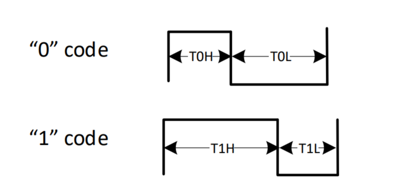
输入码型时序
逻辑电平时序
各设备中,码 0 和码 1 的高低电平持续时间有所不同。
以 WS2812B-2020 智能 LED 为例:
code0_code1_timing 码
描述
时间范围
单位
T0H
码0,高电平时间
220 ~ 380
ns
T0L
码0,低电平时间
580 ~ 1000
ns
T1H
码1,高电平时间
580 ~ 1000
ns
T1L
码1,低电平时间
220 ~ 420
ns
RESET
帧复位,低电平时间
> 280
μs
则编码总时间:
码 0:800ns ~ 1380ns
码 1:800ns ~ 1420ns
编码时间配置
通过调节寄存器中的
TxH_CNT和TxL_CNT参数,可以灵活设置码 0,码 1 的高低电平持续的时钟周期数目。x: 指 0 或 1
计数时钟:XTAL40MHz
数据传输时序
LED 通信模式
以 WS2812B LED 为例,其使用单路非归零(NRZ)通信协议,采用级联方式进行数据传输:
上电复位:LED 上电后,通过 DI 端口从控制器接收数据。首颗 LED 将采集前 24 位数据并锁存。
数据传递:剩余的数据通过内部整形电路从 DO 端口传输到下一颗 LED。
信号递减:每经过一颗 LED,信号中会减少 24 位数据。
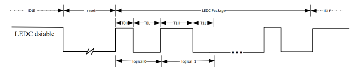
LEDC 传输时序
LEDC 发送给首个 LED 的数据时序如下:
LED 数量
支持的 LED 数量计算公式为:
LED_NUM = (1 / LED refresh rate (frame/s) - 280 μs) / ((logical 0 or 1 coding time) * 24)
以表 code0_code1_timing 中码 0 和码 1 的时序为例,计算出支持的 LED 数量:
当 LED 的刷新率为 30 帧/秒时,支持的 LED 数量为 681 ~ 1023 个。
当 LED 的刷新率为 60 帧/秒时,支持的 LED 数量为 337 ~ 853 个。
应用示例
raw_ledc_ws2812 展示了如何使用 LEDC 模块来配置和控制多个 LED 灯珠。
备注
要了解示例支持的芯片,请查看示例路径下的 README.md 文件。
Raw API
LEDC Exported Types
-
struct LEDC_InitTypeDef
LEDC Init Structure Definition.
Public Members
-
u32 led_count
Number of external LED lamps connected. This parameter can be a value of LEDC LED Number.
-
u32 data_length
Total transfer data length in 32-bit units. This parameter can be a value of LEDC Data Length.
-
u32 t1h_ns
Logical "1" high level cycle count.
-
u32 t1l_ns
Logical "1" low level cycle count.
-
u32 t0h_ns
Logical "0" high level cycle count.
-
u32 t0l_ns
Logical "0" low level cycle count.
-
u32 reset_ns
LED reset signal cycle count N. This parameter can be a value of LEDC Reset Count.
-
u32 wait_data_time_ns
FIFO data wait timeout cycle count N. This parameter can be a value of LEDC Wait Data Time Count.
-
u32 wait_time0_en
Enable or disable wait time0 insertion between two LED data packets. This parameter can be: ENABLE or DISABLE.
-
u32 wait_time1_en
Enable or disable wait time1 insertion between two LED frame data. This parameter can be: ENABLE or DISABLE.
-
u32 wait_time0_ns
Wait time0 between two LED data packets, cycle count N. This parameter can be a value of LEDC Wait Time0 Count.
-
u32 wait_time1_ns
Wait time1 between two LED frame data, cycle count N. This parameter can be a value of LEDC Wait Time1 Count.
-
u32 output_RGB_mode
RGB byte output order. This parameter can be a value of LEDC RGB Mode.
-
u32 ledc_polarity
Output signal idle level. This parameter can be a value of LEDC Idle Level.
-
u32 ledc_trans_mode
Data transfer mode (CPU or DMA). This parameter can be a value of LEDC Transfer Mode.
-
u32 ledc_fifo_level
FIFO trigger level threshold (0 to 31). A DMA or CPU request is generated when the remaining FIFO space exceeds this value. This parameter can be a value of LEDC FIFO Level.
-
u32 led_count
LEDC Exported Constants
LEDC Data Length
/* Maximum LEDC transfer data length (8192 entries). */
#define LEDC_MAX_DATA_LENGTH (0x2000)

/* Checks if the data length parameter is within valid range. */
#define IS_LEDC_DATA_LENGTH ((LENGTH > 0) && ((LENGTH) <= LEDC_MAX_DATA_LENGTH))
LEDC FIFO Level
/* LEDC internal FIFO total depth (32 entries). */
#define LEDC_FIFO_DEPTH (32)

/* Default LEDC FIFO trigger level for DMA/CPU requests. */
#define LEDC_DEFAULT_FIFO_TRIG_LEVEL (15)
LEDC Idle Level
/* LEDC output idle level is low. */
#define LEDC_IDLE_POLARITY_LOW (0)

/* LEDC output idle level is high. */
#define LEDC_IDLE_POLARITY_HIGH (1)
LEDC Input Order
/* LEDC input data bit order: LSB first. */
#define LEDC_INPUT_LSB (0)

/* LEDC input data bit order: MSB first. */
#define LEDC_INPUT_MSB (1)

/* Checks if the input bit order parameter is valid. */
#define IS_LEDC_INPUT_ORDER ((ORDER) == LEDC_INPUT_LSB || \
    (ORDER) == LEDC_INPUT_MSB)
LEDC Interrupt
/* Bitmask for all LEDC interrupt sources. */
#define LEDC_INT_ALL ((u32)0x0000001F)

/* Bitmask for all externally-enabled LEDC interrupt sources. */
#define LEDC_INT_EXT_EN ((u32)0x0000001D)

/* Checks if the interrupt parameter is within valid range. */
#define IS_LEDC_INTERRUPT ((INT) <= LEDC_INT_ALL)
LEDC LED Number
/* Default number of LEDs connected to LEDC. */
#define LEDC_DEFAULT_LED_NUM (32)

/* Maximum number of LEDs supported by LEDC (1024). */
#define LEDC_MAX_LED_NUM (1024)

/* Checks if the LED number parameter is within valid range. */
#define IS_LEDC_LED_NUM ((NUM > 0) && (NUM <= LEDC_MAX_LED_NUM))
LEDC Output Order
/* Bitmask for the LEDC output byte order field. */
#define LEDC_OUTPUT_ORDER_MASK ((u32)0x0000001C)

/* Sets the LEDC output byte order field value. */
#define LEDC_OUTPUT_ORDER ((u32)((x) & 0x00000007) << 2)
LEDC RGB Mode
/* LEDC RGB output order: GRB. */
#define LEDC_OUTPUT_GRB (0)

/* LEDC RGB output order: GBR. */
#define LEDC_OUTPUT_GBR (1)

/* LEDC RGB output order: RGB. */
#define LEDC_OUTPUT_RGB (2)

/* LEDC RGB output order: BGR. */
#define LEDC_OUTPUT_BGR (3)

/* LEDC RGB output order: RBG. */
#define LEDC_OUTPUT_RBG (4)

/* LEDC RGB output order: BRG. */
#define LEDC_OUTPUT_BRG (5)

/* Checks if the RGB output mode parameter is valid. */
#define IS_LEDC_OUTPUT_MODE ((MODE) == LEDC_OUTPUT_GRB || \
    (MODE) == LEDC_OUTPUT_GBR || \
    (MODE) == LEDC_OUTPUT_RGB || \
    (MODE) == LEDC_OUTPUT_BGR || \
    (MODE) == LEDC_OUTPUT_RBG || \
    (MODE) == LEDC_OUTPUT_BRG)
LEDC Reset Count
/* Minimum LEDC LED reset count value (0). */
#define LEDC_MIN_RESET_CNT ((u32)0)

/* Maximum LEDC LED reset count value (0x3FFF). */
#define LEDC_MAX_RESET_CNT ((u32)0x3FFF)

/* Checks if the reset count value is within valid range. */
#define IS_LEDC_RESET_VAL ((NUM) <= LEDC_MAX_RESET_CNT)
LEDC Transfer Mode
/* LEDC CPU transfer mode. */
#define LEDC_CPU_MODE (0)

/* LEDC DMA transfer mode. */
#define LEDC_DMA_MODE (1)

/* Checks if the transfer mode parameter is valid. */
#define IS_LEDC_TRANS_MODE (((MODE) == LEDC_CPU_MODE ||\
    (MODE) == LEDC_DMA_MODE))
LEDC Wait Data Time Count
/* Minimum LEDC wait-data timeout count value (0). */
#define LEDC_MIN_WAIT_DATA_TIME_CNT ((u32)0)

/* Maximum LEDC wait-data timeout count value (0x7FFF). */
#define LEDC_MAX_WAIT_DATA_TIME_CNT ((u32)0x7FFF)

/* Checks if the wait-data time count is within valid range. */
#define IS_LEDC_WAIT_DATA_TIME_VAL ((NUM) <= LEDC_MAX_WAIT_DATA_TIME_CNT)
LEDC Wait Time0 Count
/* Minimum LEDC wait time0 count value (0). */
#define LEDC_MIN_WAIT_TIME0_CNT ((u32)0)

/* Maximum LEDC wait time0 count value (0x1FF). */
#define LEDC_MAX_WAIT_TIME0_CNT ((u32)0x1FF)

/* Checks if the wait time0 count is within valid range. */
#define IS_LEDC_WAIT_TIME0_VAL ((NUM) <= LEDC_MAX_WAIT_TIME0_CNT)
LEDC Wait Time1 Count
/* Minimum LEDC wait time1 count value (0). */
#define LEDC_MIN_WAIT_TIME1_CNT ((u32)0)

/* Maximum LEDC wait time1 count value (0x7FFFFFFF). */
#define LEDC_MAX_WAIT_TIME1_CNT ((u32)0x7FFFFFFF)

/* Checks if the wait time1 count is within valid range. */
#define IS_LEDC_WAIT_TIME1_VAL ((NUM) <= LEDC_MAX_WAIT_TIME1_CNT)
LEDC Exported Functions
-
void LEDC_ClearINT(LEDC_TypeDef *LEDCx, u32 LEDC_IT)
Clear the LEDC's interrupt bits.
- 参数:
LEDCx -- Selected LEDC peripheral.
LEDC_IT --
Specifies the LEDCx interrupt sources to be cleared. This parameter can be one or combinations of the following values:
BIT_LEDC_FIFO_OVERFLOW_INT_EN: LEDC FIFO Overflow Interrupt
BIT_LEDC_WAITDATA_TIMEOUT_INT_EN: LEDC Wait Data Timeout Interrupt
BIT_LEDC_CPUREQ_FIFO_INT_EN: LEDC CPU Request Interrupt
BIT_LEDC_TRANS_FINISH_INT_EN: LEDC Transfer Finish Interrupt
-
void LEDC_Cmd(LEDC_TypeDef *LEDCx, u8 NewState)
Enable or disable LEDC peripheral.
- 参数:
LEDCx -- Selected LEDC peripheral.
NewState -- New state of the operation mode. This parameter can be: ENABLE or DISABLE.
-
u32 LEDC_GetFIFOLevel(LEDC_TypeDef *LEDCx)
Get LEDC FIFO Level.
- 参数:
LEDCx -- Selected LEDC peripheral.
- 返回:
LEDC FIFO level
-
u32 LEDC_GetINT(LEDC_TypeDef *LEDCx)
Get LEDC interrupt status.
- 参数:
LEDCx -- Selected LEDC peripheral.
- 返回:
Current interrupt status, each bit of this value represents one interrupt status:
bit 17 : FIFO_EMPTY FIFO empty status flag.
0 : FIFO is not empty
1 : FIFO is empty
bit 16 : FIFO_FULL FIFO full status flag.
0 : FIFO is not full
1 : FIFO is full
bit 3 : FIFO_OVERFLOW_INT FIFO overflow interrupt.
0 : FIFO does not overflow
1 : FIFO overflows
bit 2 : WAITDATA_TIMEOUT_INT Wait data timeout interrupt.
0 : LEDC is not timeout
1 : LEDC is timeout
bit 1 : FIFO_CPUREQ_INT CPU request interrupt when FIFO space is less than threshold.
0 : FIFO doesn't request CPU for data
1 : FIFO requests CPU to transfer data
bit 0 : LED_TRANS_FINISH_INT Transfer done interrupt.
0 : Data transfer has not completed
1 : Data transfer has completed
-
u32 LEDC_GetTransferMode(LEDC_TypeDef *LEDCx)
Get LEDC transfer mode.
- 参数:
LEDCx -- Selected LEDC peripheral.
- 返回:
LEDC transfer mode:
LEDC_DMA_MODE
LEDC_CPU_MODE
-
void LEDC_INTConfig(LEDC_TypeDef *LEDCx, u32 LEDC_IT, u32 NewState)
ENABLE/DISABLE LEDC's interrupt bits.
- 参数:
LEDCx -- Selected LEDC peripheral.
LEDC_IT --
Specifies the LEDCx interrupt sources to be enabled or disabled. This parameter can be one or combinations of the following values:
BIT_LEDC_FIFO_OVERFLOW_INT_EN: LEDC FIFO Overflow Interrupt
BIT_LEDC_WAITDATA_TIMEOUT_INT_EN: LEDC Wait Data Timeout Interrupt
BIT_LEDC_CPUREQ_FIFO_INT_EN: LEDC CPU Request Interrupt
BIT_LEDC_TRANS_FINISH_INT_EN: LEDC Transfer Finish Interrupt
NewState --
Specifies the state of the interrupt. This parameter can be one of the following values:
ENABLE
DISABLE
-
void LEDC_Init(LEDC_TypeDef *LEDCx, LEDC_InitTypeDef *LEDC_InitStruct)
Initialize the LEDC peripheral according to the specified parameters in the LEDC_InitStruct.
- 参数:
LEDCx -- Selected LEDC peripheral.
LEDC_InitStruct -- Pointer to a LEDC_InitTypeDef structure that contains the configuration information for the specified LEDC peripheral
-
void LEDC_LEDReset(LEDC_TypeDef *LEDCx)
Set LEDC Send LED refresh signal.
- 参数:
LEDCx -- Selected LEDC peripheral.
-
u32 LEDC_SendData(LEDC_TypeDef *LEDCx, void *data, u32 Len)
Send Specific Data to LEDC FIFO.
- 参数:
LEDCx -- Selected LEDC peripheral.
data -- LEDCx input source data, only the lower 24bits valid.
Len -- Data length to send.
- 返回:
Number of data items actually sent to LEDC FIFO.
-
void LEDC_SetFIFOLevel(LEDC_TypeDef *LEDCx, u8 FifoLevel)
Set LEDC's FIFO Level.
- 参数:
LEDCx -- Selected LEDC peripheral.
FifoLevel -- LEDCx FIFO level. Value range: 0 to 31. When the number of transmit FIFO entries is greater or equal to this value, DMA request or BIT_LEDC_CPUREQ_FIFO_INT_EN happens. This parameter is recommended to 7 or 15.
-
void LEDC_SetInputMode(LEDC_TypeDef *LEDCx, u8 order)
Set LEDC Input MSB or LSB order.
- 参数:
LEDCx -- Selected LEDC peripheral.
order --
This parameter can be one of the following values:
LEDC_INPUT_LSB: LSB first
LEDC_INPUT_MSB: MSB first
-
void LEDC_SetLEDNum(LEDC_TypeDef *LEDCx, u32 Num)
Set LEDC LED Number.
- 参数:
LEDCx -- Selected LEDC peripheral.
Num -- LEDCx LED number. Value range: 1 to 1024.
-
void LEDC_SetOutputMode(LEDC_TypeDef *LEDCx, u32 mode)
Set LEDC Output RGB Mode.
- 参数:
LEDCx -- Selected LEDC peripheral.
mode --
LEDCx Output mode with input GBR mode order. This parameter can be one of the following values:
LEDC_OUTPUT_GRB: LEDC Output in order of GRB
LEDC_OUTPUT_GBR: LEDC Output in order of GBR
LEDC_OUTPUT_RGB: LEDC Output in order of RGB
LEDC_OUTPUT_BGR: LEDC Output in order of BGR
LEDC_OUTPUT_RBG: LEDC Output in order of RBG
LEDC_OUTPUT_BRG: LEDC Output in order of BRG
-
void LEDC_SetOutputOrder(LEDC_TypeDef *LEDCx, u8 order)
Set LEDC Output data with MSB or LSB order.
- 参数:
LEDCx -- Selected LEDC peripheral.
order --
Specifies the output order, can be one of the following values:
LEDC_INPUT_LSB: LEDC input data in order of GRB
LEDC_INPUT_MSB: LEDC input data in order of GBR
-
void LEDC_SetPolarity(LEDC_TypeDef *LEDCx, u32 Pol)
Set LEDC Idle Output Level.
- 参数:
LEDCx -- Selected LEDC peripheral.
Pol --
LEDCx Output level. This parameter can be one of the following values:
LEDC_IDLE_POLARITY_HIGH: LEDC Idle output High Level
LEDC_IDLE_POLARITY_LOW: LEDC Idle output Low Level
-
void LEDC_SetReset_val(LEDC_TypeDef *LEDCx, u32 RstVal)
Set LEDC Reset Time Value.
- 参数:
LEDCx -- Selected LEDC peripheral.
RstVal -- LEDC reset time Value. Value range is LEDC_MIN_RESET_CNT to LEDC_MAX_RESET_CNT.
-
void LEDC_SetT0H_val(LEDC_TypeDef *LEDCx, u32 T0hVal)
Set LEDC logic 0 high level time.
- 参数:
LEDCx -- Selected LEDC peripheral.
T0hVal -- LEDC logic 0 high level time. Value Range is 0 to 0x7F.
-
void LEDC_SetT0L_val(LEDC_TypeDef *LEDCx, u32 T0lVal)
Set LEDC logic 0 low level time.
- 参数:
LEDCx -- Selected LEDC peripheral.
T0lVal -- LEDC logic 0 low level time. Value Range is 0 to 0x7F.
-
void LEDC_SetT1H_val(LEDC_TypeDef *LEDCx, u32 T1hVal)
Set LEDC logic 1 high level time.
- 参数:
LEDCx -- Selected LEDC peripheral.
T1hVal -- LEDC logic 1 high level time. Value Range is 0 to 0x7F.
-
void LEDC_SetT1L_val(LEDC_TypeDef *LEDCx, u32 T1lVal)
Set LEDC logic 1 low level time.
- 参数:
LEDCx -- Selected LEDC peripheral.
T1lVal -- LEDC logic 1 low level time. Value Range is 0 to 0x7F.
-
void LEDC_SetTotalLength(LEDC_TypeDef *LEDCx, u32 TotalData)
Set LEDC Total Data Length.
- 参数:
LEDCx -- Selected LEDC peripheral.
TotalData -- LEDCx data length. Value range: 1 to 8192. This specifies total amount of 32-bit data words to transfer.
-
void LEDC_SetTransferMode(LEDC_TypeDef *LEDCx, u32 mode)
Set LEDC transfer mode.
- 参数:
LEDCx -- Selected LEDC peripheral.
mode --
This parameter can be one of the following values:
LEDC_CPU_MODE
LEDC_DMA_MODE
-
void LEDC_SetWaitDataTime_val(LEDC_TypeDef *LEDCx, u32 WaitDataVal)
Set LEDC Wait data Time Value.
- 参数:
LEDCx -- Selected LEDC peripheral.
WaitDataVal -- LEDC wait data. Value range is LEDC_MIN_WAIT_DATA_TIME_CNT to LEDC_MAX_WAIT_DATA_TIME_CNT.
-
void LEDC_SetWaitTime0_val(LEDC_TypeDef *LEDCx, u32 WaitTime0, u8 NewState)
Set LEDC Wait between Two Packages Time0 Value.
- 参数:
LEDCx -- Selected LEDC peripheral.
WaitTime0 -- LEDC wait time0. Value range is LEDC_MIN_WAIT_TIME0_CNT to LEDC_MAX_WAIT_TIME0_CNT.
NewState --
Enable or disable wait time between two packages. This parameter can be one of the following values:
ENABLE
DISABLE
-
void LEDC_SetWaitTime1_val(LEDC_TypeDef *LEDCx, u32 WaitTime1, u8 NewState)
Set LEDC Wait between Two Frames Time1 Value.
- 参数:
LEDCx -- Selected LEDC peripheral.
WaitTime1 -- LEDC wait time1. Value range is LEDC_MIN_WAIT_TIME1_CNT to LEDC_MAX_WAIT_TIME1_CNT.
NewState --
Enable or disable wait time between two frames. This parameter can be one of the following values:
ENABLE
DISABLE
-
void LEDC_SoftReset(LEDC_TypeDef *LEDCx)
Set LEDC soft reset, Force LEDC Enters IDLE State.
- 参数:
LEDCx -- Selected LEDC peripheral.
备注
LEDC soft reset will clear to 0 after set 1; after LEDC soft reset, LEDC enters idle state, which brings all interrupt status cleared, FIFO read write pointer cleared, finished data count is 0 and LEDC_EN bit is cleared to 0.
-
void LEDC_StructInit(LEDC_InitTypeDef *LEDC_InitStruct)
Fill each LEDC_InitStruct member with its default value.
- 参数:
LEDC_InitStruct -- Pointer to an LEDC_InitTypeDef structure which will be initialized.
-
bool LEDC_TXGDMA_Init(LEDC_TypeDef *LEDCx, PGDMA_InitTypeDef GDMA_InitStruct, void *CallbackData, IRQ_FUN CallbackFunc, u32 *pTxData, u32 Length)
Init and Enable LEDC TX GDMA.
- 参数:
LEDCx -- Selected LEDC peripheral.
GDMA_InitStruct -- Pointer to a GDMA_InitTypeDef structure that contains the configuration information for the GDMA peripheral.
CallbackData -- GDMA callback data.
CallbackFunc -- GDMA callback function.
pTxData -- Tx Buffer.
Length -- Tx Count.
- 返回:
Init status:
TRUE: Init success
FALSE: Init fail
-
void LEDC_WriteData(LEDC_TypeDef *LEDCx, u32 data)
Write Data to LEDC FIFO.
- 参数:
LEDCx -- Selected LEDC peripheral.
data -- LEDCx input data, only the lower 24bits valid.