LCD 控制器(LCDC)
概述
芯片集成了液晶显示控制器(LCDC),用于驱动 LCD 面板,为嵌入式系统提供灵活且高效的显示解决方案。
功能特性
支持标准 RGB 并行和 I80 (MCU) 接口
支持丰富的接口位宽与像素格式
高度可配置的时序控制参数
内置像素格式转换器(PFC)
支持多种中断类型
架构与接口
系统架构
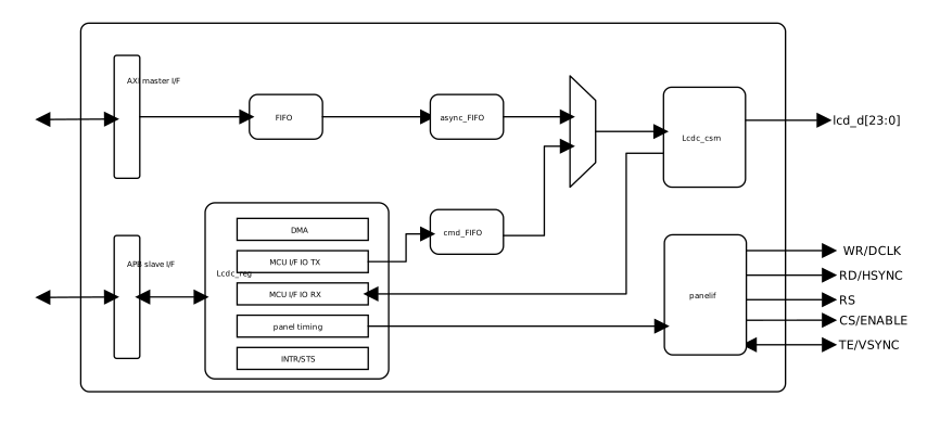
LCDC 架构
接口信号
RGB 接口信号
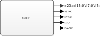
RGB 接口信号
可编程时序控制
时序参数:VSW, VBP, VFP, HSW, HBP 和 HFP 宽度
极性参数:HSYNC, VSYNC, DE, DCLK。
辅助控制信号
显示面板接口通常包含 LCDC 接口信号之外的其他必要信号:
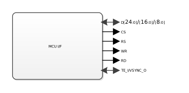
接口位宽及色深
接口类型 |
6bit-RGB565 |
8bit-RGB565 |
8bit-RGB888 |
16bit-RGB565 |
24bit-RGB888 |
|---|---|---|---|---|---|
RGB 接口 |
✓ |
✓ |
✓ |
✓ |
|
I80 接口 |
✓ |
✓ |
✓ |
✓ |
数据同步与处理
帧同步模式
提供两种帧同步模式,可依据 LCD 时序要求进行灵活选择:
HV 模式:通过 HSYNC 和 VSYNC 信号同步。
DE 模式:通过 DE 信号同步。
提供两种帧同步模式,可依据 LCD 时序要求进行灵活选择:
TE 模式 : LCDC 响应 LCD 的 TE 信号,在预设延迟后传输像素数据。
VSYNC 模式 :LCDC 基于内部的 VSYNC 信号,按 VSYNC 节奏发送像素数据。
像素格式转换器
支持在内存中的像素格式与接口数据格式之间的实时转换。转换过程遵循以下规则:
Alpha 通道处理 :若源格式包含 Alpha 值,直接舍弃。
高位深向低位深转换 :舍弃高位深格式的低位数据
示例:RGB888 转 RGB565

低位深向高位深转换 :使用高位数据填充高位深格式的低位
示例:RGB565 转 RGB888

中断机制
提供细致的中断管理功能,以适应高效的事件响应需求:
帧开始中断
帧结束中断
行命中中断
TE (Tearing Effect)信号中断
FIFO 下溢中断 (underflow)
双缓冲 Ping-Pong 机制
背景
某些LCD没有内置图形存储器(GRAM),需要主控持续推送像素数据到屏幕。
单缓冲区的问题
使用单一帧缓冲器时,存在以下风险:
CPU 正在更新的不完整帧数据可能被直接显示在屏幕上,导致画面闪烁或显示错误的中间状态。
通常使用多重缓冲技术(例如双缓冲)来避免该行为。
双缓冲区解决方案
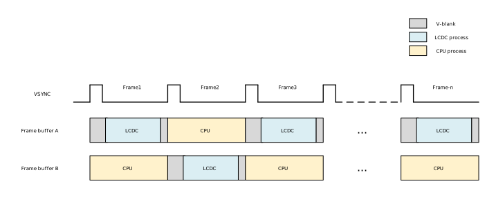
使用两个独立的缓冲区进行 Ping-Pong:
显示缓冲区 :当前 LCDC 推送到屏幕的完整帧
绘制缓冲区 :CPU准备下一帧的工作区域
完成一帧显示后,两个缓冲区角色互换,确保屏幕始终接收完整帧数据,如图所示。
开发流程
前期准备
准备一块 LCD,并查阅其文档,确认以下信息:
接口类型 :为后续软硬件操作奠定基础
接口信号 :确保正确的硬件连接和驱动配置
时序参数 :如采样时钟边沿等
备注
当屏幕文档无法满足上述需求时,请查阅屏幕驱动芯片文档。
警告
对于 MCU 接口 LCD:请务必获取正确的初始化序列,初始化错误可能导致显示异常。
硬件设计
芯片封装选型
确保足够的引脚数量以满足接口信号需求。
备注
部分封装引脚数量有限,可能无法支持复杂接口。
LCD 子板集成配置指南
Realtek 提供专业 LCD 转板,配备 FPC 接口和母口排针,用于连接屏幕 PCB 底板与 Ameba EVB。
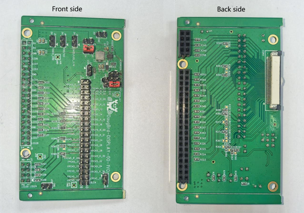
信号映射确认 :查阅 EVB 和 LCD 子板原理图,确认信号与引脚对应关系。
电阻上件检查 :按需进行电阻 rework, 确保信号连通。
电源规划 :确认供电和接地连接完整性。
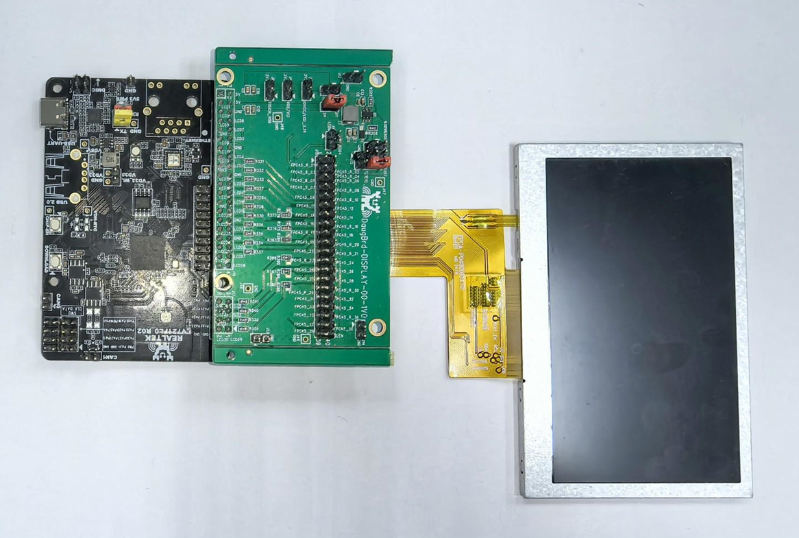
LCD 面板连接
使用 LCD 转板将 EVB 与 LCD 面板进行连接。
软件开发
编程要点
引脚复用配置
使能 LCDC 外设的时钟
初始化结构体以配置时序参数
初始化 LCDC 硬件寄存器
配置帧缓冲区地址到寄存器
使能 LCDC 外设
代码分析
引脚复用配置
通用信号
对于 背光 和 硬件复位 等通用信号,可使用 GPIO 控制。
RGB 接口时序信号
请参考 引脚复用,调用
Pinmux_Config(PinName, FuncId)进行配置。
备注
接口位宽最大支持 24-bit;
当接口位宽小于 24-bit 时,Function-ID 需从 LCD_D0 开始使用。
例如,对于 16-bit RGB565,Function-ID 仅支持 LCD_D0~LCD_D15,不支持 LCD_D8~LCD_D23。
分配 GRAM 并填充像素数据
需记录分配的内存首地址(如 0x60001000),以便在步骤 5 中配置给 LCDC。
使能 LCDC 功能及时钟
LCDC_RccEnable()
根据 LCD 手册初始化 LCDC
获取并配置以下信息:接口宽度、图像分辨率、像素格式、HV 参数(vsw, vbp, vfp, hsw, hbp, hfp)、信号极性等。
备注
接口宽度与输出像素格式需在 接口位宽及色深 范围内配置,否则可能无法显示。
帧率不能低于 LCD 要求,否则可能无法显示。
示例配置(24-bit RGB888,480x800):
void LCDC_RGBStructInit(LCDC_RGBInitTypeDef *LCDC_RGBInitStruct)
{
   /* 配置 LCD 参数 */
   LCDC_RGBInitStruct->Panel_Init.IfWidth = LCDC_RGB_IF_24_BIT;
   LCDC_RGBInitStruct->Panel_Init.ImgHeight = 480;
   LCDC_RGBInitStruct->Panel_Init.ImgWidth = 800;
   LCDC_RGBInitStruct->Panel_Init.InputFormat = LCDC_INPUT_FORMAT_RGB888;
   LCDC_RGBInitStruct->Panel_Init.OutputFormat = LCDC_OUTPUT_FORMAT_RGB888;
   LCDC_RGBInitStruct->Panel_Init.RGBRefreshFreq = 35;

   /* 配置信号 H/V 参数 */
   LCDC_RGBInitStruct->Panel_RgbTiming.RgbVsw = 1;
   LCDC_RGBInitStruct->Panel_RgbTiming.RgbVbp = 4;
   LCDC_RGBInitStruct->Panel_RgbTiming.RgbVfp = 6;

   LCDC_RGBInitStruct->Panel_RgbTiming.RgbHsw = 4;
   LCDC_RGBInitStruct->Panel_RgbTiming.RgbHbp = 40;
   LCDC_RGBInitStruct->Panel_RgbTiming.RgbHfp = 40;

   /* 配置信号极性 */
   LCDC_RGBInitStruct->Panel_RgbTiming.Flags.RgbEnPolar = LCDC_RGB_EN_PUL_HIGH_LEV_ACTIVE;
   LCDC_RGBInitStruct->Panel_RgbTiming.Flags.RgbHsPolar = LCDC_RGB_HS_PUL_LOW_LEV_SYNC;
   LCDC_RGBInitStruct->Panel_RgbTiming.Flags.RgbVsPolar = LCDC_RGB_VS_PUL_LOW_LEV_SYNC;
   LCDC_RGBInitStruct->Panel_RgbTiming.Flags.RgbDclkActvEdge = LCDC_RGB_DCLK_FALLING_EDGE_FETCH;
}

/* 初始化 LCDC */
LCDC_RGBInit(LCDC, &LCDC_RGBInitStruct);
根据步骤 2 分配的地址,配置给 LCDC
LCDC_DMAImgCfg(LCDC, 0x60001000);
使能 LCDC
LCDC_Cmd(LCDC, ENABLE);
备注
如果 LCD 需要初始化操作,请根据其指定通信接口补充以下配置:
硬件配置
保证 Ameba 的通信引脚正确连接至 LCD 的通信信号。
软件配置
初始化通信接口。
发送 LCD 初始命令序列。
编程要点
引脚复用配置
使能 LCDC 外设的时钟
初始化结构体以配置时序参数
初始化 LCDC 硬件寄存器
配置帧缓冲区地址到寄存器
使能 LCDC 外设
发送控制命令初始化 LCD
代码分析
引脚复用配置
通用信号
背光和硬件复位等通用信号可通过 GPIO 进行控制。
MCU 接口时序信号
请参考 引脚复用 章节,依次调用
Pinmux_Config(PinName, FuncId)进行必要的配置。
备注
接口位宽最大支持 24-bit;
当接口位宽小于 24-bit 时,Function-ID 需从 LCD_D0 开始使用。
例如,对于 16-bit RGB565,Function-ID 仅支持 LCD_D0~LCD_D15,不支持 LCD_D8~LCD_D23。
分配 GRAM 并填充像素数据
记录分配到的内存首地址(如 0x60001000)以供后续配置给 LCDC。
使能 LCDC 功能和时钟
LCDC_RccEnable()
初始化 MCU 进入 IO 模式
请查阅 LCD 手册,进行如下配置。
void LCDC_MCUStructInit(LCDC_MCUInitTypeDef *LCDC_MCUInitStruct)
{
   /* 配置面板参数 */
   LCDC_MCUInitStruct->Panel_Init.IfWidth = LCDC_MCU_IF_8_BIT;
   LCDC_MCUInitStruct->Panel_Init.ImgWidth = 240;
   LCDC_MCUInitStruct->Panel_Init.ImgHeight = 320;
   LCDC_MCUInitStruct->Panel_Init.InputFormat = LCDC_INPUT_FORMAT_RGB565;
   LCDC_MCUInitStruct->Panel_Init.OutputFormat = LCDC_OUTPUT_FORMAT_RGB565;

   /* 配置信号极性 */
   LCDC_MCUInitStruct->Panel_McuTiming.McuRdPolar = LCDC_MCU_RD_PUL_RISING_EDGE_FETCH;
   LCDC_MCUInitStruct->Panel_McuTiming.McuWrPolar = LCDC_MCU_WR_PUL_RISING_EDGE_FETCH;
   LCDC_MCUInitStruct->Panel_McuTiming.McuRsPolar = LCDC_MCU_RS_PUL_LOW_LEV_CMD_ADDR;
   LCDC_MCUInitStruct->Panel_McuTiming.McuTePolar = LCDC_MCU_TE_PUL_LOW_LEV_ACTIVE;
   LCDC_MCUInitStruct->Panel_McuTiming.McuSyncPolar = LCDC_MCU_VSYNC_PUL_LOW_LEV_ACTIVE;
}

/* 初始化 LCDC */
LCDC_MCUInit(LCDC, &LCDC_MCUInitStruct);
/* 使能 LCDC */
LCDC_Cmd(LCDC, ENABLE);
发送命令序列以初始化 LCD
发送命令和参数的接口分别为:
/* 发送命令 */
LCDC_MCUIOWriteCmd(LCDC, cmd);
/* 发送命令参数 */
LCDC_MCUIOWriteData(LCDC, data);
小心
请设置正确的初始化序列,否则可能无法正常显示。
设置预设命令,以写 Ram 的命令码 0x2C 为例
/* 设置预设命令: write_ram */
u8 wram_cmd = 0x2C;
LCDC_MCUSetPreCmd(LCDC, &wram_cmd, 1);
切换 IO 模式至 DMA 模式
/* 关闭 LCDC */
LCDC_Cmd(LCDC, DISABLE);

Lcdc_McuDmaCfgDef LCDC_MCUDmaCfgStruct;
/* 设定同步方式 */
LCDC_MCUDmaCfgStruct.TeMode = 0;  /* DISABLE */
/* 设定 DMA 模式 */
LCDC_MCUDmaCfgStruct.TriggerDma = LCDC_TRIGGER_DMA_MODE;
LCDC_MCUDmaMode(LCDC, &LCDC_MCUDmaCfgStruct);
根据步骤 2 分配的地址,配置给 LCDC
LCDC_DMAImgCfg(LCDC, 0x60001000);
使能 LCDC
LCDC_Cmd(LCDC, ENABLE);
在需要更新像素数据时,触发 LCDC 发送像素数据
LCDC_MCUDMATrigger(LCDC);
应用示例
SDK 提供了如下功能示例,帮助开发者了解和使用 LCDC 功能:
raw_lcdc_rgb_st7262 演示如何使用
RGB 接口DMA自动模式驱动 RGB LCD;raw_lcdc_srgb_st7272a 演示如何使用 RGB 接口驱动
SRGB LCD;raw_lcdc_mcu_ili9806 演示如何使用
MCU 接口DMA触发模式驱动 MCU LCD。
备注
要了解示例支持的芯片,请查看示例路径下的 README.md 文件。
Raw API
LCDC Exported Types
-
struct LCDC_InitTypeDef
LCDC Init Structure Definition.
Public Members
-
u16 LCDC_ImageWidth
Specifies the width of the display image in pixels.
-
u16 LCDC_ImageHeight
Specifies the height of the display image in pixels.
-
u8 LCDC_BgColorRed
Specifies the red component of the background color. Value range: 0x00 to 0xFF.
-
u8 LCDC_BgColorGreen
Specifies the green component of the background color. Value range: 0x00 to 0xFF.
-
u8 LCDC_BgColorBlue
Specifies the blue component of the background color. Value range: 0x00 to 0xFF.
-
LCDC_LayerConfigTypeDef layerx[LCDC_LAYER_MAX_NUM]
Specifies the configuration for each display layer.
-
u16 LCDC_ImageWidth
-
struct LCDC_LayerConfigTypeDef
LCDC Layer Init Structure Definition.
Public Members
-
u8 LCDC_LayerEn
Specifies layer enable or not. This parameter can be a value of ENABLE or DISABLE
-
u8 LCDC_LayerImgFormat
Specifies the layer image data format. This parameter can be a value of LCDC Layer IMG Format
-
u8 LCDC_LayerColorKeyingEn
Specifies the layer's color keying enable or not. This parameter can be a value of ENABLE or DISABLE
-
u32 LCDC_LayerImgBaseAddr
Specifies the image base address. This parameter can be a number between 0x0 and 0xffffffff.
-
u16 LCDC_LayerHorizontalStart
Specifies the first pixel of a line of the layer window. This parameter can be a number between 0x0 and 0xfff.
-
u16 LCDC_LayerHorizontalStop
Specifies the last pixel of a line of the layer window. This parameter can be a number between 0x0 and 0xfff.
-
u16 LCDC_LayerVerticalStart
Specifies the first line of the layer window. This parameter can be a number between 0x0 and 0xfff.
-
u16 LCDC_LayerVerticalStop
Specifies the last line of the layer window. This parameter can be a number between 0x0 and 0xfff.
-
u32 LCDC_LayerColorKeyingVal
Specifies the color key value (RGB), which is used by the Color Keying. This parameter can be a number between 0x0 and 0xffffff.
-
u8 LCDC_LayerBlendConfig
Specifies the blending factor. This parameter can be a value of 0 (const alpha) or 1 (pixel alpha x constant alpha)
-
u8 LCDC_LayerConstAlpha
Specifies the Constant Alpha used for blending. This parameter can be a number between 0x00 and 0xff. Hardware divides the Constant Alpha value by 256. When Constant Alpha is 0xFF, it is identified as 1.
-
u8 LCDC_LayerEn
-
struct LCDC_DMAImgAdvanceDef
LCDC Shift CfgInfo Definition.
Public Members
-
u32 ImgAddrA
Specifies the base address of image A. DMA skips pixels based on ImgOfstDotX/ImgOfstLineY and then fetches from this address.
-
u32 ImgAddrB
Specifies the base address of image B. DMA fetches from the initial position with a length of ImgOfstDotX/ImgOfstLineY.
-
u32 ImgOfstDotX
Specifies the horizontal pixel offset for image slide. Must be a multiple of 4. Cannot be non-zero simultaneously with ImgOfstLineY.
-
u32 ImgOfstLineY
Specifies the vertical line offset for image slide. Cannot be non-zero simultaneously with ImgOfstDotX.
-
u32 ImgAddrA
-
struct LCDC_MCUInitTypeDef
LCDC MCU I/F Mode Initialization structure definition.
Public Members
-
Panel_InitDef Panel_Init
Specifies the panel configuration, including interface width, image size, and color format.
-
Panel_McuTimingDef Panel_McuTiming
Specifies the MCU signal timing configuration, including pulse polarity settings.
-
Panel_InitDef Panel_Init
-
enum LCDC_MCU_RUN_MODE
LCDC Run Mode Definition.
Values:
/* DMA transfer mode. */
LCDC_MCU_RUN_DMA_MODE = 0

/* Direct I/O access mode. */
LCDC_MCU_RUN_IO_MODE
-
struct LCDC_RGBInitTypeDef
LCDC RGB I/F Mode Initialization structure definition.
Public Members
-
Panel_InitDef Panel_Init
Specifies the panel configuration, including interface width, image size, and color format.
-
Panel_RgbTimingDef Panel_RgbTiming
Specifies the RGB signal timing configuration, including HSYNC/VSYNC parameters and signal polarities.
-
Panel_InitDef Panel_Init
-
enum LCDC_ShiftDir
LCDC Shift Direction Definition.
Values:
/* Shift function disabled. */
LCDC_SHIFT_DISABLE = 0

/* Shift direction: left to right. */
LCDC_SHIFT_DIR_L2R

/* Shift direction: right to left. */
LCDC_SHIFT_DIR_R2L

/* Shift direction: top to bottom. */
LCDC_SHIFT_DIR_T2B

/* Shift direction: bottom to top. */
LCDC_SHIFT_DIR_B2T
-
struct LCDC_ShiftInfoDef
LCDC Shift BkupInfo Definition.
Public Members
-
u32 Direction
Specifies the shift direction. This parameter can be a value of LCDC_ShiftDir.
-
u32 SliceTotal
Specifies the total number of shift slices.
-
u32 SliceIdx
Specifies the current slice index.
-
u32 SlotX
Specifies the horizontal slot size in pixels.
-
u32 SlotY
Specifies the vertical slot size in pixels.
-
u32 ImgW
Specifies the image width in pixels.
-
u32 ImgH
Specifies the image height in pixels.
-
u32 Direction
-
struct Lcdc_McuDmaCfgDef
Public Members
-
u16 TriggerDma
Specifies the DMA trigger mode. 1: one-shot trigger mode, 0: auto-refresh mode.
-
u16 TeMode
Specifies whether TE synchronization is enabled. 1: TE mode enabled, 0: TE mode disabled.
-
u32 TeDelay
Specifies the delay from the TE signal to frame transfer start. Unit: WR pulse width. Must be >= 5.
-
u16 TriggerDma
-
struct Panel_InitDef
Public Members
-
u32 IfWidth
Specifies the LCDC MCU Interface Mode. This parameter can be a value of LCDC MCU IF Width Define in MCU I/F MODE, This parameter can be a value of LCDC RGB IF Width Define in RGB I/F MODE
-
u32 ImgHeight
Specifies the height of the LCDC plane size. This parameter can be a number between 0x000 and 0xfff.
-
u32 ImgWidth
Specifies the width of the LCDC plane size. This parameter can be a number between 0x000 and 0xfff.
-
u32 InputFormat
Specifies the input format. This parameter can be a value LCDC Input Format Define.
-
u32 OutputFormat
Specifies the output format. This parameter can be a value LCDC Output Format Define.
-
u32 RGBRefreshFreq
Specifies the RGB frame refresh frequency. This parameter can be a number between 0x000 and 0xfff.
-
u32 IfWidth
-
struct Panel_McuTimingDef
Public Members
-
u8 McuSyncPolar
Specifies the LCDC MCU vsync pulse polarity. This parameter can be a value of LCDC MCU VSYNC Pulse Polarity Define.
-
u8 McuTePolar
Specifies the LCDC MCU TE pulse polarity. This parameter can be a value of LCDC MCU TE Pulse Polarity Define.
-
u8 McuRdPolar
Specifies the LCDC MCU read pulse polarity. This parameter can be a value of LCDC MCU Read Pulse Polarity Define.
-
u8 McuWrPolar
Specifies the LCDC MCU write pulse polarity. This parameter can be a value of LCDC MCU Write Pulse Polarity Define.
-
u8 McuRsPolar
Specifies the LCDC MCU RS pulse polarity. This parameter can be a value of LCDC MCU RS Pulse Polarity Define.
-
u8 McuSyncPolar
-
struct Panel_RgbTimingDef
Public Members
-
u32 RgbVfp
Specifies the front porch line number. This parameter can be a number between 0x1 and 0x10. Unit: line
-
u32 RgbVbp
Specifies the back porch line number. This parameter can be a number between 0x1 and 0x10. Unit: line
-
u32 RgbVsw
Specifies the vertical sync signal width. This parameter can be a number between 0x1 and 0x10. Unit: line
-
u32 RgbHfp
Specifies the horizontal front porch. This parameter can be a number between 0x01 and 0x100. Unit: DCLK
-
u32 RgbHbp
Specifies the horizontal back porch. This parameter can be a number between 0x01 and 0x100. Unit: DCLK
-
u32 RgbHsw
Specifies the horizontal sync signal width. This parameter can be a number between 0x01 and 0x100. Unit: DCLK
-
struct Panel_RgbTimingDef.Panel_RgbSignalPolarityDef Flags
-
struct Panel_RgbTimingDef.Panel_RgbSignalPolarityDef
-
u8 RgbEnPolar
Specifies the RGB ENABLE pulse polarity. This parameter can be a value of LCDC RGB Enable Pulse Polarity Define
-
u8 RgbHsPolar
Specifies the RGB HSYNC pulse polarity. This parameter can be a value of LCDC RGB HSYNC Pulse Polarity Define
-
u8 RgbVsPolar
Specifies the RGB VSYNC pulse polarity. This parameter can be a value of LCDC RGB VSYNC Pulse Polarity Define
-
u8 RgbDclkActvEdge
Specifies the RGB DCLK active edge. This parameter can be a value of LCDC RGB DCLK Active Edge Define
-
u8 RgbEnPolar
-
u32 RgbVfp
LCDC Exported Constants
LCDC IT Clear
/* Validates that IT is a legal LCDC interrupt clear bitmask. */
#define IS_LCDC_CLEAR_IT ((((IT) & (u32)0xFFFFFFD2) == 0x00) && ((IT) != 0x00))
Not supported.
LCDC DMA Underflow Mode
/* DMA underflow outputs last valid data. */
#define LCDC_DMAUNFW_OUTPUT_LASTDATA (0)

/* DMA underflow outputs configured error data. */
#define LCDC_DMAUNFW_OUTPUT_ERRORDATA (LCDC_BIT_DMA_UN_MODE)

/* Validates that MODE is a legal DMA underflow output mode. */
#define IS_LCDC_DMA_DMA_UNDERFLOW_MODE (((MODE) == LCDC_DMAUNFW_OUTPUT_LASTDATA) || ((MODE) == LCDC_DMAUNFW_OUTPUT_ERRORDATA))
Not supported.
LCDC DMA Debug Out
/* Enable secondary DMA write-back debug output. */
#define LCDC_DMA_OUT_ENABLE LCDC_BIT_LCD_DMA_OUT

/* Disable secondary DMA write-back debug output. */
#define LCDC_DMA_OUT_DISABLE (0)

/* Validates that MODE is a legal DMA debug output mode. */
#define IS_LCDC_DMA_DEBUG_OUT_MODE (((MODE) == LCDC_DMA_OUT_ENABLE) || ((MODE) == LCDC_DMA_OUT_DISABLE))
Not supported.
LCDC Layer Burst Size
/* DMA burst size: 1 x 64 bytes per burst. */
#define LCDC_LAYER_BURSTSIZE_1X64BYTES (0x1)

/* DMA burst size: 2 x 64 bytes per burst. */
#define LCDC_LAYER_BURSTSIZE_2X64BYTES (0x2)

/* DMA burst size: 3 x 64 bytes per burst. */
#define LCDC_LAYER_BURSTSIZE_3X64BYTES (0x3)

/* DMA burst size: 4 x 64 bytes per burst. */
#define LCDC_LAYER_BURSTSIZE_4X64BYTES (0x4)

/* Validates that x is a legal layer DMA burst size. */
#define IS_LCDC_LAYER_BURSTSIZE (((u32)(x) - 1) < LCDC_LAYER_BURSTSIZE_4X64BYTES)
Not supported.
LCDC Layer IMG Format
/* Layer image format: ARGB8888 (32-bit). */
#define LCDC_LAYER_IMG_FORMAT_ARGB8888 (0x0)

/* Layer image format: RGB888 (24-bit). */
#define LCDC_LAYER_IMG_FORMAT_RGB888 (0x1)

/* Layer image format: RGB565 (16-bit). */
#define LCDC_LAYER_IMG_FORMAT_RGB565 (0x2)

/* Layer image format: ARGB1555 (16-bit with 1-bit alpha). */
#define LCDC_LAYER_IMG_FORMAT_ARGB1555 (0x3)

/* Layer image format: ARGB4444 (16-bit with 4-bit alpha). */
#define LCDC_LAYER_IMG_FORMAT_ARGB4444 (0x4)

/* Layer image format: RGB666 (18-bit). */
#define LCDC_LAYER_IMG_FORMAT_RGB666 (0x5)

/* Layer image format: ARGB8666 (32-bit with 8-bit alpha). */
#define LCDC_LAYER_IMG_FORMAT_ARGB8666 (0x6)

/* Validates that MODE is a legal layer image format. */
#define IS_LCDC_LAYER_IMG_FORMAT ((u32)(MODE) <= LCDC_LAYER_IMG_FORMAT_ARGB8666)
Not supported.
LCDC Layer ID
/* LCDC layer index: layer 1 (first layer). */
#define LCDC_LAYER_LAYER1 (0x0)

/* LCDC layer index: layer 2 (second layer). */
#define LCDC_LAYER_LAYER2 (0x1)

/* LCDC layer index: layer 3 (third layer). */
#define LCDC_LAYER_LAYER3 (0x2)

/* Total number of available LCDC layers. */
#define LCDC_LAYER_MAX_NUM (0x3)

/* Validates that LayerID is a legal LCDC layer index. */
#define IS_LCDC_A_VALID_LAYER ((u32)(LayerID) <= LCDC_LAYER_LAYER3)
Not supported.
LCDC MCU IF Width Define
Not supported.
/* MCU 8-bit interface mode, supports RGB565/RGB888 */
#define LCDC_MCU_IF_8_BIT (0x0)

/* MCU 16-bit interface mode, supports RGB565 */
#define LCDC_MCU_IF_16_BIT (0x1)

/* MCU 24-bit interface mode, supports RGB888 */
#define LCDC_MCU_IF_24_BIT (0x4)

/* Check whether the parameter is a valid LCDC MCU interface width mode. */
#define IS_LCDC_MCU_IF_MODE (((MODE) == LCDC_MCU_IF_8_BIT) || \
    ((MODE) == LCDC_MCU_IF_16_BIT) || \
    ((MODE) == LCDC_MCU_IF_9_BIT) || \
    ((MODE) == LCDC_MCU_IF_18_BIT) || \
    ((MODE) == LCDC_MCU_IF_24_BIT))
LCDC RGB IF Width Define
Not supported.
/* RGB 6-bit parallel interface mode, supports RGB565/RGB666 */
#define LCDC_RGB_IF_6_BIT (0x8)

/* RGB 16-bit parallel interface mode, supports RGB565 */
#define LCDC_RGB_IF_16_BIT (0x9)

/* RGB 8-bit parallel interface mode, supports RGB888 */
#define LCDC_RGB_IF_8_BIT (0xb)

/* RGB 24-bit parallel interface mode, supports RGB888 */
#define LCDC_RGB_IF_24_BIT (0xc)

/* Check whether the parameter is a valid LCDC RGB interface width mode. */
#define IS_LCDC_RGB_IF_MODE (((MODE) == LCDC_RGB_IF_6_BIT) || \
    ((MODE) == LCDC_RGB_IF_16_BIT) || \
    ((MODE) == LCDC_RGB_IF_18_BIT) || \
    ((MODE) == LCDC_RGB_IF_8_BIT) || \
    ((MODE) == LCDC_RGB_IF_24_BIT))
LCDC DMA Underflow Mode Define
Not supported.
/* DMA underflow outputs last valid data */
#define LCDC_DMA_UNDFLW_OUTPUT_LASTDATA (0x0)

/* DMA underflow outputs configured error data */
#define LCDC_DMA_UNDFLW_OUTPUT_ERRORDATA (0x1)

/* Check if LCDC DMA underflow output mode is valid. */
#define IS_LCDC_DMA_UNDFLOW_MODE (((MODE) == LCDC_DMA_UNDFLW_OUTPUT_LASTDATA) || \
    ((MODE) == LCDC_DMA_UNDFLW_OUTPUT_ERRORDATA))
LCDC DMA Underflow Option Define
Not supported.
/* Instantly output error data on current frame at underflow */
#define LCDC_DMA_UNDFLOW_INSTANT_ERRDATA_CURFRAME (0x0)

/* Pause then output error data on current frame at underflow */
#define LCDC_DMA_UNDFLOW_PAUSE_ERRDATA_CURFRAME (0x1)

/* Instantly enter drop mode at underflow */
#define LCDC_DMA_UNDFLOW_INSTANT_DROP_LINE (0x2)

/* Pause then enter drop mode at underflow */
#define LCDC_DMA_UNDFLOW_PAUSE_DROP_LINE (0x3)

/* Check if LCDC DMA underflow option is valid. */
#define IS_LCDC_DMA_UNDFLOW_OPTION (((OPT) == LCDC_DMA_UNDFLOW_INSTANT_ERRDATA_CURFRAME) || \
    ((OPT) == LCDC_DMA_UNDFLOW_PAUSE_ERRDATA_CURFRAME) || \
    ((OPT) == LCDC_DMA_UNDFLOW_INSTANT_DROP_LINE) || \
    ((OPT) == LCDC_DMA_UNDFLOW_PAUSE_DROP_LINE))
LCDC DMA Mode Define
Not supported.
/* DMA auto-refresh mode */
#define LCDC_AUTO_DMA_MODE (0x0)

/* DMA manual trigger mode */
#define LCDC_TRIGGER_DMA_MODE (0x1)

/* Check if LCDC DMA mode is valid. */
#define IS_LCDC_DMA_MODE (((MODE) == LCDC_AUTO_DMA_MODE) || \
    ((MODE) == LCDC_TRIGGER_DMA_MODE))
LCDC DMA Burst Size
Not supported.
/* DMA burst size: 1x64 bytes (AXI 64-byte burst). */
#define LCDC_DMA_BURSTSIZE_1X64BYTES (0x0)

/* DMA burst size: 2x64 bytes (AXI 128-byte burst). */
#define LCDC_DMA_BURSTSIZE_2X64BYTES (0x1)

/* DMA burst size: 4x64 bytes (AXI 256-byte burst). */
#define LCDC_DMA_BURSTSIZE_4X64BYTES (0x2)

/* Check if LCDC DMA burst size is valid. */
#define IS_LCDC_DMA_BURSTSIZE (((x) == LCDC_DMA_BURSTSIZE_1X64BYTES) || \
    ((x) == LCDC_DMA_BURSTSIZE_2X64BYTES) || \
    ((x) == LCDC_DMA_BURSTSIZE_4X64BYTES) )
LCDC INTR Type Define
Not supported.
/* Bitmask of all valid LCDC interrupt type bits. */
#define LCDC_INTR_TYPE_MASK (LCDC_BIT_FRM_START_INTEN | \
    LCDC_BIT_IO_TIMEOUT_INTEN | \
    LCDC_BIT_LCD_LIN_INTEN | \
    LCDC_BIT_LCD_FRD_INTEN | \
    LCDC_BIT_PANEL_TE_INTEN | \
    LCDC_BIT_DMA_UN_INTEN)

/* Check if LCDC interrupt type bitmask is valid. */
#define IS_LCDC_INTR_TYPE (((TYPE) & (~LCDC_INTR_TYPE_MASK)) == 0)
LCDC INTR Status Define
Not supported.
/* Bitmask of all LCDC interrupt status bits. */
#define LCDC_INTR_STATUS_ALL_BITS (LCDC_BIT_FRM_START_INTS | \
    LCDC_BIT_IO_TIMEOUT_INTS | \
    LCDC_BIT_LCD_LIN_INTS | \
    LCDC_BIT_LCD_FRD_INTS | \
    LCDC_BIT_PANEL_TE_INTS | \
    LCDC_BIT_DMA_UN_INTS)

/* Check if LCDC interrupt status bitmask is valid. */
#define IS_LCDC_INTR_STATUS (((TYPE) & ~LCDC_INTR_STATUS_ALL_BITS) == 0)
LCDC RGB Sync Mode Define
Not supported.
/* RGB DE (data enable) synchronization mode. */
#define LCDC_RGB_DE_MODE (0)

/* RGB HV (HSYNC/VSYNC) synchronization mode. */
#define LCDC_RGB_HV_MODE (1)

/* RGB TE (tearing effect) synchronization mode. */
#define LCDC_RGB_TE_MODE (2)

/* Check if LCDC RGB synchronization mode is valid. */
#define IS_LCDC_RGB_SYNC_MODE (((MODE) == LCDC_RGB_DE_MODE) || \
    ((MODE) == LCDC_RGB_HV_MODE) || \
    ((MODE) == LCDC_RGB_TE_MODE))
LCDC RGB DMA Mode Define
Not supported.
/* RGB DMA auto-refresh mode. */
#define LCDC_RGB_DMA_AUTO_MODE (0)

/* RGB DMA manual trigger mode. */
#define LCDC_RGB_DMA_TRIGGER_MODE (1)

/* Check if LCDC RGB DMA mode is valid. */
#define IS_LCDC_RGB_DMA_MODE (((MODE) == LCDC_RGB_DMA_AUTO_MODE) || \
    ((MODE) == LCDC_RGB_DMA_TRIGGER_MODE) )
LCDC RGB Data Pulse Polarity Define
Not supported.
/* RGB data pulse polarity: normal. */
#define LCDC_RGB_DAT_PUL_NORMAL (0)

/* RGB data pulse polarity: inverted. */
#define LCDC_RGB_DAT_PUL_INVERT (1)

/* Check if LCDC RGB data pulse polarity is valid. */
#define IS_LCDC_RGB_DAT_PUL_POLARITY (((POLARITY) == LCDC_RGB_DAT_PUL_NORMAL) || \
    ((POLARITY) == LCDC_RGB_DAT_PUL_INVERT))
LCDC RGB Enable Pulse Polarity Define
Not supported.
/* RGB ENABLE pulse: low level active. */
#define LCDC_RGB_EN_PUL_LOW_LEV_ACTIVE (0)

/* RGB ENABLE pulse: high level active. */
#define LCDC_RGB_EN_PUL_HIGH_LEV_ACTIVE (1)

/* Check if LCDC RGB enable pulse polarity is valid. */
#define IS_LCDC_RGB_EN_PUL_POLARITY (((POLARITY) == LCDC_RGB_EN_PUL_LOW_LEV_ACTIVE) || \
    ((POLARITY) == LCDC_RGB_EN_PUL_HIGH_LEV_ACTIVE))
LCDC RGB HSYNC Pulse Polarity Define
Not supported.
/* RGB HSYNC pulse: low level synchronization. */
#define LCDC_RGB_HS_PUL_LOW_LEV_SYNC (0)

/* RGB HSYNC pulse: high level synchronization. */
#define LCDC_RGB_HS_PUL_HIGH_LEV_SYNC (1)

/* Check if LCDC RGB HSYNC pulse polarity is valid. */
#define IS_LCDC_RGB_HS_PUL_POLARITY (((POLARITY) == LCDC_RGB_HS_PUL_LOW_LEV_SYNC) || \
    ((POLARITY) == LCDC_RGB_HS_PUL_HIGH_LEV_SYNC))
LCDC RGB VSYNC Pulse Polarity Define
Not supported.
/* RGB VSYNC pulse: low level synchronization. */
#define LCDC_RGB_VS_PUL_LOW_LEV_SYNC (0)

/* RGB VSYNC pulse: high level synchronization. */
#define LCDC_RGB_VS_PUL_HIGH_LEV_SYNC (1)

/* Check if LCDC RGB VSYNC pulse polarity is valid. */
#define IS_LCDC_RGB_VS_PUL_POLARITY (((POLARITY) == LCDC_RGB_VS_PUL_LOW_LEV_SYNC) || \
    ((POLARITY) == LCDC_RGB_VS_PUL_HIGH_LEV_SYNC))
LCDC RGB DCLK Active Edge Define
Not supported.
/* RGB DCLK: data fetched at rising edge. */
#define LCDC_RGB_DCLK_RISING_EDGE_FETCH (0)

/* RGB DCLK: data fetched at falling edge. */
#define LCDC_RGB_DCLK_FALLING_EDGE_FETCH (1)

/* Check if LCDC RGB DCLK edge selection is valid. */
#define IS_LCDC_RGB_DCLK_EDGE (((EDGE) == LCDC_RGB_DCLK_RISING_EDGE_FETCH) || \
    ((EDGE) == LCDC_RGB_DCLK_FALLING_EDGE_FETCH))
LCDC RGB TE Pulse Polarity Define
Not supported.
/* RGB TE pulse: low level active. */
#define LCDC_RGB_TE_PUL_LOW_LEV_SYNC (0)

/* RGB TE pulse: high level active. */
#define LCDC_RGB_TE_PUL_HIGH_LEV_SYNC (1)

/* Check if LCDC RGB TE pulse polarity is valid. */
#define IS_LCDC_RGB_TE_PUL_POLARITY (((POLARITY) == LCDC_RGB_TE_PUL_LOW_LEV_SYNC) || \
    ((POLARITY) == LCDC_RGB_TE_PUL_HIGH_LEV_SYNC))
LCDC MCU Swap Define
Not supported.
/* MCU data byte swap disabled. */
#define LCDC_MCU_SWAP_DISABLE (0)

/* MCU data byte swap enabled. */
#define LCDC_MCU_SWAP_ENABLE (1)

/* Check if LCDC MCU byte swap mode is valid. */
#define IS_LCDC_MCU_SWAP_MODE (((MODE) == LCDC_MCU_SWAP_DISABLE) || \
    ((MODE) == LCDC_MCU_SWAP_ENABLE))
LCDC MCU Mode Define
Not supported.
/* MCU DMA transfer mode. */
#define LCDC_MCU_DMA_MODE (0)

/* MCU I/O direct access mode. */
#define LCDC_MCU_IO_MODE (1)

/* Check if LCDC MCU transfer mode is valid. */
#define IS_LCDC_MCU_MODE (((MODE) == LCDC_MCU_IO_MODE) || \
    ((MODE) == LCDC_MCU_DMA_MODE))
LCDC MCU Sync Mode Define
Not supported.
/* MCU synchronized with internal clock. */
#define LCDC_MCU_SYNC_WITH_INTERNAL_CLK (0)

/* MCU synchronized with VSYNC input. */
#define LCDC_MCU_SYNC_WITH_VSYNC (1)

/* MCU synchronized with tearing effect (TE) signal. */
#define LCDC_MCU_SYNC_WITH_TE (2)

/* Check if LCDC MCU synchronization mode is valid. */
#define IS_LCDC_MCU_SYNC_MODE (((MODE) == LCDC_MCU_SYNC_WITH_INTERNAL_CLK) || \
    ((MODE) == LCDC_MCU_SYNC_WITH_VSYNC) || \
    ((MODE) == LCDC_MCU_SYNC_WITH_TE))
LCDC MCU VSYNC Pulse Polarity Define
Not supported.
/* MCU VSYNC pulse: low level active. */
#define LCDC_MCU_VSYNC_PUL_LOW_LEV_ACTIVE (0)

/* MCU VSYNC pulse: high level active. */
#define LCDC_MCU_VSYNC_PUL_HIGH_LEV_ACTIVE (1)

/* Check if LCDC MCU VSYNC pulse polarity is valid. */
#define IS_LCDC_MCU_VSYNC_PUL_POLARITY (((POL) == LCDC_MCU_VSYNC_PUL_LOW_LEV_ACTIVE) || \
    ((POL) == LCDC_MCU_VSYNC_PUL_HIGH_LEV_ACTIVE))
LCDC MCU TE Pulse Polarity Define
Not supported.
/* MCU TE pulse: low level active. */
#define LCDC_MCU_TE_PUL_LOW_LEV_ACTIVE (0)

/* MCU TE pulse: high level active. */
#define LCDC_MCU_TE_PUL_HIGH_LEV_ACTIVE (1)

/* Check if LCDC MCU TE pulse polarity is valid. */
#define IS_LCDC_MCU_TE_PUL_POLARITY (((POL) == LCDC_MCU_TE_PUL_LOW_LEV_ACTIVE) || \
    ((POL) == LCDC_MCU_TE_PUL_HIGH_LEV_ACTIVE))
LCDC MCU Data Pulse Polarity Define
Not supported.
/* MCU data pulse polarity: normal. */
#define LCDC_MCU_DAT_PUL_NORMAL (0)

/* MCU data pulse polarity: inverted. */
#define LCDC_MCU_DAT_PUL_INVERT (1)

/* Check if LCDC MCU data pulse polarity is valid. */
#define IS_LCDC_MCU_DAT_PUL_POLARITY (((POLARITY) == LCDC_MCU_DAT_PUL_NORMAL) || \
    ((POLARITY) == LCDC_MCU_DAT_PUL_INVERT))
LCDC MCU Read Pulse Polarity Define
Not supported.
/* MCU RD pulse: data fetched at rising edge. */
#define LCDC_MCU_RD_PUL_RISING_EDGE_FETCH (0)

/* MCU RD pulse: data fetched at falling edge. */
#define LCDC_MCU_RD_PUL_FALLING_EDGE_FETCH (1)

/* Check if LCDC MCU read pulse polarity is valid. */
#define IS_LCDC_MCU_RD_PUL_POLARITY (((POLARITY) == LCDC_MCU_RD_PUL_RISING_EDGE_FETCH) || \
    ((POLARITY) == LCDC_MCU_RD_PUL_FALLING_EDGE_FETCH))
LCDC MCU Write Pulse Polarity Define
Not supported.
/* MCU WR pulse: data fetched at rising edge. */
#define LCDC_MCU_WR_PUL_RISING_EDGE_FETCH (0)

/* MCU WR pulse: data fetched at falling edge. */
#define LCDC_MCU_WR_PUL_FALLING_EDGE_FETCH (1)

/* Check if LCDC MCU write pulse polarity is valid. */
#define IS_LCDC_MCU_WR_PUL_POLARITY (((POLARITY) == LCDC_MCU_WR_PUL_RISING_EDGE_FETCH) || \
    ((POLARITY) == LCDC_MCU_WR_PUL_FALLING_EDGE_FETCH))
LCDC MCU RS Pulse Polarity Define
Not supported.
/* MCU RS pulse: low level for command address. */
#define LCDC_MCU_RS_PUL_LOW_LEV_CMD_ADDR (0)

/* MCU RS pulse: high level for data (parameter). */
#define LCDC_MCU_RS_PUL_HIGH_LEV_CMD_ADDR (1)

/* Check if LCDC MCU RS pulse polarity is valid. */
#define IS_LCDC_MCU_RS_PUL_POLARITY (((POLARITY) == LCDC_MCU_RS_PUL_LOW_LEV_CMD_ADDR) || \
    ((POLARITY) == LCDC_MCU_RS_PUL_HIGH_LEV_CMD_ADDR))
LCDC MCU CS Pulse Polarity Define
Not supported.
/* MCU CS pulse: low level active. */
#define LCDC_MCU_CS_PUL_LOW_LEV_ACTIVE (0)

/* MCU CS pulse: high level active. */
#define LCDC_MCU_CS_PUL_HIGH_LEV_ACTIVE (1)

/* Check if LCDC MCU CS pulse polarity is valid. */
#define IS_LCDC_MCU_CS_PUL_POLARITY (((POLARITY) == LCDC_MCU_CS_PUL_LOW_LEV_ACTIVE) || \
    ((POLARITY) == LCDC_MCU_CS_PUL_HIGH_LEV_ACTIVE))
LCDC Input Format Define
Not supported.
/* Input image format: ARGB8888. */
#define LCDC_INPUT_FORMAT_ARGB8888 (0x0)

/* Input image format: RGB888. */
#define LCDC_INPUT_FORMAT_RGB888 (0x1)

/* Input image format: RGB565. */
#define LCDC_INPUT_FORMAT_RGB565 (0x2)

/* Input image format: ABGR8888. */
#define LCDC_INPUT_FORMAT_ABGR8888 (0x8)

/* Input image format: BGR888. */
#define LCDC_INPUT_FORMAT_BGR888 (0x9)

/* Input image format: BGR565. */
#define LCDC_INPUT_FORMAT_BGR565 (0xa)

/* Check if LCDC input image format is valid. */
#define IS_LCDC_INPUT_FORMAT (((MODE) <= LCDC_INPUT_FORMAT_BGR565) && ((MODE) != 0x7))
LCDC Output Format Define
Not supported.
/* Output panel format: RGB888. */
#define LCDC_OUTPUT_FORMAT_RGB888 (0x0)

/* Output panel format: RGB565. */
#define LCDC_OUTPUT_FORMAT_RGB565 (0x1)

/* Output panel format: BGR888. */
#define LCDC_OUTPUT_FORMAT_BGR888 (0x8)

/* Output panel format: BGR565. */
#define LCDC_OUTPUT_FORMAT_BGR565 (0x9)

/* Check if LCDC output image format is valid. */
#define IS_LCDC_OUTPUT_FORMAT (((MODE) == LCDC_OUTPUT_FORMAT_RGB888) || \
    ((MODE) == LCDC_OUTPUT_FORMAT_RGB565) || \
    ((MODE) == LCDC_OUTPUT_FORMAT_RGB666) || \
    ((MODE) == LCDC_OUTPUT_FORMAT_BGR888) || \
    ((MODE) == LCDC_OUTPUT_FORMAT_BGR565) || \
    ((MODE) == LCDC_OUTPUT_FORMAT_BGR666) )
LCDC Pre-Command Define
Not supported.
/* Maximum number of pre-command DWORDs. */
#define LCDC_CMD_DWORD_MAX 4

/* Maximum number of MCU pre-command bytes. */
#define LCDC_MCU_PRECMD_MAX_NUM 16

/* Initial value for one 4-byte command group. */
#define LCDC_CMD_GROUP_INITIAL_VAL 0x00000000

/* Bitmask for one MCU command byte. */
#define LCDC_MASK_MCU_CMD_BYTE ((u8)0x000000FF << 0)

/* Set one MCU command byte value. */
#define LCDC_MCU_CMD_BYTE ((u8)((x) & 0x000000FF) << 0)
LCDC Shift Offset Define
Not supported.
/* Invalid shift offset value (shift function disabled). */
#define LCDC_SHIFT_OFST_INVALID 0x0
LCDC RW Parameter
Not supported.
/* MCU write cycle period in nanoseconds. */
#define LCDC_WRITE_CYCLE_PERIOD_NS (60)

/* MCU read cycle period in nanoseconds. */
#define LCDC_READ_CYCLE_PERIOD_NS (800)
LCDC Peripheral Definitions
Not supported.
/* Check whether the peripheral is the LCDC instance. */
#define IS_LCDC_ALL_PERIPH (PERIPH == LCDC)
LCDC Exported Functions
LCDC Interrupt Functions
-
void LCDC_ClearAllINT(LCDC_TypeDef *LCDCx)
Clear all of the LCDC interrupt pending bits.
- 参数:
LCDCx -- Where LCDCx can be LCDC.
-
void LCDC_LineINTPosConfig(LCDC_TypeDef *LCDCx, u32 LineNum)
Configure line interrupt position.
- 参数:
LCDCx -- Where LCDCx can be LCDC.
LineNum -- The specific line number at which the line interrupt is triggered.
-
void LCDC_ClearINT(LCDC_TypeDef *LCDCx, u32 LCDC_IT)
Clear the LCDC's interrupt pending bits.
- 参数:
LCDCx -- Where LCDCx can be LCDC.
LCDC_IT --
Specifies the interrupt to be cleared. This parameter can be any combination of the following values:
LCDC_BIT_FRM_START_INTS: DMA frame start interrupt
LCDC_BIT_LCD_LIN_INTS: Line interrupt
LCDC_BIT_LCD_FRD_INTS: LCD refresh frame done interrupt
LCDC_BIT_DMA_UN_INTS: DMA FIFO underflow interrupt
-
u32 LCDC_GetINTStatus(LCDC_TypeDef *LCDCx)
Get LCDC interrupt status.
- 参数:
LCDCx -- Where LCDCx can be LCDC.
- 返回:
The interrupt status register value. Each bit indicates an interrupt source:
LCDC_BIT_FRM_START_INTS: DMA frame start interrupt status
LCDC_BIT_LCD_LIN_INTS: Line interrupt status
LCDC_BIT_LCD_FRD_INTS: LCD refresh frame done interrupt status
LCDC_BIT_DMA_UN_INTS: DMA FIFO underflow interrupt status
-
u32 LCDC_GetRawINTStatus(LCDC_TypeDef *LCDCx)
Get LCDC Raw Interrupt Status.
- 参数:
LCDCx -- Where LCDCx can be LCDC.
- 返回:
The raw interrupt status register value. Each bit indicates an interrupt source:
LCDC_BIT_FRM_START_INTRS: DMA frame start raw interrupt status
LCDC_BIT_LCD_LIN_INTRS: Line raw interrupt status
LCDC_BIT_LCD_FRD_INTRS: LCD refresh frame done raw interrupt status
LCDC_BIT_DMA_UN_INTRS: DMA FIFO underflow raw interrupt status
-
void LCDC_INTConfig(LCDC_TypeDef *LCDCx, u32 LCDC_IT, u32 NewState)
Enable or disable the specified LCDC interrupts.
- 参数:
LCDCx -- Where LCDCx can be LCDC.
LCDC_IT --
Specifies the LCDC interrupts sources to be enabled or disabled. This parameter can be any combination of the following values:
LCDC_BIT_FRM_START_INTEN: DMA frame start interrupt
LCDC_BIT_LCD_LIN_INTEN: Line interrupt
LCDC_BIT_LCD_FRD_INTEN: LCD refresh frame done interrupt
LCDC_BIT_DMA_UN_INTEN: DMA FIFO underflow interrupt
NewState -- New state of the specified LCDC interrupts. This parameter can be: ENABLE or DISABLE.
-
void LCDC_GetDmaUnINTCnt(LCDC_TypeDef *LCDCx, u32 *DmaUnIntCnt)
Get the DMA FIFO underflow interrupt count.
- 参数:
LCDCx -- Where LCDCx can be LCDC.
DmaUnIntCnt -- The DMA underflow interrupt count pointer.
-
void LCDC_ClearINT(LCDC_TypeDef *LCDCx, u32 LCDC_IT)
Clear the LCDC's interrupt pending bits.
- 参数:
LCDCx -- Where LCDCx can be LCDC.
LCDC_IT --
Specifies the interrupt to be cleared. This parameter can be any combination of the following values:
LCDC_BIT_PANEL_TE_INTS: Panel TE input interrupt
LCDC_BIT_FRM_START_INTS: DMA frame start interrupt
LCDC_BIT_IO_TIMEOUT_INTS: Write or read timeout interrupt
LCDC_BIT_LCD_LIN_INTS: Line interrupt
LCDC_BIT_LCD_FRD_INTS: LCD refresh frame done interrupt
LCDC_BIT_DMA_UN_INTS: DMA FIFO underflow interrupt
-
u32 LCDC_GetINTStatus(LCDC_TypeDef *LCDCx)
Get LCDC interrupt status.
- 参数:
LCDCx -- Where LCDCx can be LCDC.
- 返回:
The interrupt status register value. Each bit indicates an interrupt source:
LCDC_BIT_PANEL_TE_INTS: Panel TE input interrupt status
LCDC_BIT_FRM_START_INTS: DMA frame start interrupt status
LCDC_BIT_IO_TIMEOUT_INTS: Write or read timeout interrupt status
LCDC_BIT_LCD_LIN_INTS: Line interrupt status
LCDC_BIT_LCD_FRD_INTS: LCD refresh frame done interrupt status
LCDC_BIT_DMA_UN_INTS: DMA FIFO underflow interrupt status
-
u32 LCDC_GetRawINTStatus(LCDC_TypeDef *LCDCx)
Get LCDC Raw Interrupt Status.
- 参数:
LCDCx -- Where LCDCx can be LCDC.
- 返回:
The raw interrupt status register value. Each bit indicates an interrupt source:
LCDC_BIT_PANEL_TE_INTRS: Panel TE input raw interrupt status
LCDC_BIT_FRM_START_INTRS: DMA frame start raw interrupt status
LCDC_BIT_IO_TIMEOUT_INTRS: Write or read timeout raw interrupt status
LCDC_BIT_LCD_LIN_INTRS: Line raw interrupt status
LCDC_BIT_LCD_FRD_INTRS: LCD refresh frame done raw interrupt status
LCDC_BIT_DMA_UN_INTRS: DMA FIFO underflow raw interrupt status
-
void LCDC_INTConfig(LCDC_TypeDef *LCDCx, u32 LCDC_IT, u32 NewState)
Enable or disable the specified LCDC interrupts.
- 参数:
LCDCx -- Where LCDCx can be LCDC.
LCDC_IT --
Specifies the LCDC interrupts sources to be enabled or disabled. This parameter can be any combination of the following values:
LCDC_BIT_PANEL_TE_INTEN: Panel TE input interrupt
LCDC_BIT_FRM_START_INTEN: DMA frame start interrupt
LCDC_BIT_IO_TIMEOUT_INTEN: Write or read timeout interrupt
LCDC_BIT_LCD_LIN_INTEN: Line interrupt
LCDC_BIT_LCD_FRD_INTEN: LCD refresh frame done interrupt
LCDC_BIT_DMA_UN_INTEN: DMA FIFO underflow interrupt
NewState -- New state of the specified LCDC interrupts. This parameter can be: ENABLE or DISABLE.
LCDC Global Functions
-
void LCDC_Cmd(LCDC_TypeDef *LCDCx, u32 NewState)
Enable or disable the LCDC.
- 参数:
LCDCx -- Where LCDCx can be LCDC.
NewState -- New state of the LCDC. This parameter can be: ENABLE or DISABLE.
备注
When NewState is DISABLE, the disable action will be performed instantly.
HW will reset LCDC internal states and disable LCDC, then clear both the disable bit and the enable bit (LCDCEN).
-
void LCDC_DeInit(LCDC_TypeDef *LCDCx)
Deinitialize the LCDC.
- 参数:
LCDCx -- Where LCDCx can be LCDC.
备注
Disable LCDC instantly, clear and disable all interrupts.
-
void LCDC_GetCurPosStatus(LCDC_TypeDef *LCDCx, u32 *pCurPosX, u32 *pCurPosY)
Get the current position.
- 参数:
LCDCx -- Where LCDCx can be LCDC.
pCurPosX -- The current X position pointer.
pCurPosY -- The current Y position pointer.
-
u8 LCDC_CheckLCDCReady(LCDC_TypeDef *LCDCx)
Check LCDC is ready to work with VO interface after LCDC is enabled.
- 参数:
LCDCx -- Where LCDCx can be LCDC.
- 返回:
Status:
TRUE: Ready
FALSE: Not ready
-
void LCDC_Init(LCDC_TypeDef *LCDCx, LCDC_InitTypeDef *LCDC_InitStruct)
Initialize the LCDC according to the specified parameters in the LCDC_InitStruct.
- 参数:
LCDCx -- Where LCDCx can be LCDC.
LCDC_InitStruct -- Pointer to a LCDC_InitTypeDef structure that contains the configuration information for all LCDC layers.
-
void LCDC_LayerConfig(LCDC_TypeDef *LCDCx, u8 LayerId, LCDC_LayerConfigTypeDef *EachLayer)
Initialize the LCDC Layer according to the specified parameters in the EachLayer.
- 参数:
LCDCx -- Where LCDCx can be LCDC.
LayerId -- Specifies the LCDC layer to configure.
EachLayer -- Pointer to a LCDC_LayerConfigTypeDef structure that contains the configuration information for the specified LCDC layer.
-
void LCDC_SetBkgColor(LCDC_TypeDef *LCDCx, u8 red_color, u8 green_color, u8 blue_color)
Set the LCDC background color.
- 参数:
LCDCx -- Where LCDCx can be LCDC.
red_color -- Red component of background color.
green_color -- Green component of background color.
blue_color -- Blue component of background color.
-
void LCDC_SetPlaneSize(LCDC_TypeDef *LCDCx, u32 ImageWidth, u32 ImageHeight)
Set the LCDC Plane Size.
- 参数:
LCDCx -- Where LCDCx can be LCDC.
ImageWidth -- The width of image (X-channel based), which means pixel number per line.
ImageHeight -- The height of image (Y-channel based)
-
void LCDC_StructInit(LCDC_InitTypeDef *LCDC_InitStruct)
Fill each LCDC_InitTypeDef member with its default value.
- 参数:
LCDC_InitStruct -- Pointer to an LCDC_InitTypeDef structure which will be initialized.
-
void LCDC_TrigerSHWReload(LCDC_TypeDef *LCDCx)
Trigger Layer's shadow register reload to apply new configuration.
- 参数:
LCDCx -- Where LCDCx can be LCDC.
备注
The shadow registers read back the active values. Until the reload has been done, the 'old' value is read.
-
void LCDC_ColorFomatInputConfig(LCDC_TypeDef *LCDCx, u32 CorlorFmtIn)
Configure LCDC input color format.
- 参数:
LCDCx -- Where LCDCx can be LCDC.
CorlorFmtIn --
Specifies the input color format. This parameter can be any following value:
LCDC_INPUT_FORMAT_ARGB8888
LCDC_INPUT_FORMAT_RGB888
LCDC_INPUT_FORMAT_RGB565
LCDC_INPUT_FORMAT_ABGR8888
LCDC_INPUT_FORMAT_BGR888
LCDC_INPUT_FORMAT_BGR565
-
void LCDC_ColorFomatOutputConfig(LCDC_TypeDef *LCDCx, u32 CorlorFmtOut)
Configure LCDC output color format.
- 参数:
LCDCx -- Where LCDCx can be LCDC.
CorlorFmtOut --
Specifies the output color format. This parameter can be any following value:
LCDC_OUTPUT_FORMAT_RGB888
LCDC_OUTPUT_FORMAT_RGB565
LCDC_OUTPUT_FORMAT_BGR888
LCDC_OUTPUT_FORMAT_BGR565
-
void LCDC_PanelSizeConfig(LCDC_TypeDef *LCDCx, uint32_t width, uint32_t height)
Configure the panel resolution for LCDC.
- 参数:
LCDCx -- Where LCDCx can be LCDC.
width -- The panel width in pixels.
height -- The panel height in lines.
-
u32 LCDC_RccEnable(void)
Enable LCDC peripheral clock and initialize clock sources.
- 返回:
LCDC system clock.
-
void LCDC_ShadowReloadConfig(LCDC_TypeDef *LCDCx)
Trigger shadow register reload to active register, to apply new configuration.
- 参数:
LCDCx -- Where LCDCx can be LCDC.
备注
The shadow registers read back the active values. Until the reload has been done, the 'old' value is read.
LCDC DMA Configure Functions
-
void LCDC_DMADebugConfig(LCDC_TypeDef *LCDCx, u32 DmaWriteBack, u32 ImgDestAddr)
Configure LCDC DMA debug write back function.
- 参数:
LCDCx -- Where LCDCx can be LCDC.
DmaWriteBack --
Secondary RGB output port enabled, the blended data of entire image will be written back to memory. this parameter can be one of the following values:
LCDC_DMA_OUT_ENABLE: Enable the debug function
LCDC_DMA_OUT_DISABLE: Disable the debug function
ImgDestAddr -- Image DMA destination address. (for debug)
-
void LCDC_DMAModeConfig(LCDC_TypeDef *LCDCx, u32 BurstSize)
Configure LCDC DMA burst size.
- 参数:
LCDCx -- Where LCDCx can be LCDC.
BurstSize --
DMA burst size; Unit 64 Bytes.
LCDC_LAYER_BURSTSIZE_1X64BYTES: Burst Transactions = 1;
LCDC_LAYER_BURSTSIZE_2X64BYTES: Burst Transactions = 2;
LCDC_LAYER_BURSTSIZE_3X64BYTES: Burst Transactions = 3;
LCDC_LAYER_BURSTSIZE_4X64BYTES: Burst Transactions = 4;
备注
If the BurstSize=1, the actual burstsize = 1x64 Bytes; If the BurstSize=2, the actual burstsize = 2x64 = 128 Bytes; etc.
The parameter "BurstSize" value range: 1 to 4.
-
void LCDC_DMAUnderFlowConfig(LCDC_TypeDef *LCDCx, u32 DmaUnFlwMode, u32 ErrorData)
Configure LCDC DMA underflow mode and underflow error data.
- 参数:
LCDCx -- Where LCDCx can be LCDC.
DmaUnFlwMode --
DMA underflow mode, this parameter can be one of the following values:
LCDC_DMAUNFW_OUTPUT_LASTDATA: output last data
LCDC_DMAUNFW_OUTPUT_ERRORDATA: output error data
ErrorData -- The output data when DMA FIFO underflow occurred. When underflow mode is configured as LCDC_DMAUNFW_OUTPUT_ERRORDATA, this parameter is needed, and otherwise it can be ignored.
-
void LCDC_DMABurstSizeConfig(LCDC_TypeDef *LCDCx, u32 BurstSize)
Configure LCDC DMA burst size.
- 参数:
LCDCx -- Where LCDCx can be LCDC.
BurstSize --
DMA burst size; Unit 64 Bytes.
LCDC_DMA_BURSTSIZE_1X64BYTES: Burst Transactions = 1;
LCDC_DMA_BURSTSIZE_2X64BYTES: Burst Transactions = 2;
LCDC_DMA_BURSTSIZE_4X64BYTES: Burst Transactions = 4;
备注
If the BurstSize=1, the actual burstsize = 1x64 Bytes; If the BurstSize=2, the actual burstsize = 2x64 = 128 Bytes; etc.
The parameter "BurstSize" is not more than 3.
-
void LCDC_DMAImageShiftConfig(LCDC_TypeDef *LCDCx, u32 ImgbufCurrent, u32 ImgbufTarget, enum LCDC_ShiftDir Direction)
Configure DMA image buffer address and offset.
- 参数:
LCDCx -- Where LCDCx can be LCDC.
ImgbufCurrent -- The current image base address-A. This parameter is always required. When the shift function is disabled, set Direction to LCDC_SHIFT_DISABLE.
ImgbufTarget -- The target image base address. If disable shift function, this parameter is ignored. If enable shift function, both ImgbufCurrent and ImgbufTarget must be set and Direction must not be LCDC_SHIFT_DISABLE.
Direction --
The shift direction. this parameter can be one of the following values:
LCDC_SHIFT_DISABLE
LCDC_SHIFT_DIR_L2R
LCDC_SHIFT_DIR_R2L
LCDC_SHIFT_DIR_T2B
LCDC_SHIFT_DIR_B2T
备注
Ensure that both ImgbufCurrent and ImgbufTarget are properly set when using the shift function.
-
void LCDC_DMAImgCfg(LCDC_TypeDef *LCDCx, u32 ImgBaseAddrA)
Configure the DMA image address where DMA will fetch pix data.
- 参数:
LCDCx -- Where LCDCx can be LCDC.
ImgBaseAddrA -- Frame buffer address.
-
void LCDC_DMAImgCfgAdvance(LCDC_TypeDef *LCDCx, const LCDC_DMAImgAdvanceDef *DmaImgInfo)
Configure DMA two image address and offset for shift function.
- 参数:
LCDCx -- Where LCDCx can be LCDC.
DmaImgInfo -- Pointer to a LCDC_DMAImgAdvanceDef structure that contains imageA/imageB address and ofst_dotX/ofst_lineY.
备注
For imageA address: where DMA skips pixels based on ofst_dotX/ofst_lineY and then starts fetching pixel data.
For imageB address: where DMA starts fetching from the initial position, with the fetch length of ofst_dotX/ofst_lineY.
The ofst_dotX/ofst_lineY cannot be non-zero simultaneously.
The ofst_dotX need to be a multiple of 4.
-
void LCDC_DMAUnderFlowOpt(LCDC_TypeDef *LCDCx, u32 DmaUnFlwOpt, u32 Threshold)
Configure LCDC DMA options when dma underflow event occurs.
- 参数:
LCDCx -- Where LCDCx can be LCDC.
DmaUnFlwOpt --
DMA underflow option, this parameter can be one of the following values:
LCDC_DMA_UNDFLOW_PAUSE_ERRDATA_CURFRAME: Pause clock and data; after timeout, output error data for the remaining frame.
LCDC_DMA_UNDFLOW_PAUSE_DROP_LINE: Pause clock and data; after timeout, drop the current line and continue transmitting the next lines.
LCDC_DMA_UNDFLOW_INSTANT_ERRDATA_CURFRAME: Do not pause clock and data; instantly output error data for the remaining frame.
LCDC_DMA_UNDFLOW_INSTANT_DROP_LINE: Do not pause clock and data; instantly drop the current line and continue transmitting the next lines. The output data can be last_data or err_data, which depends on the LCDC_BIT_DMA_UN_MODE config.
Threshold -- The timeout threshold value when dma underflow occurred. When DmaUnFlwOpt is configured as LCDC_DMA_UNDFLOW_PAUSE_ERRDATA_CURFRAME or LCDC_DMA_UNDFLOW_PAUSE_DROP_LINE, this parameter is needed, otherwise it can be ignored.
-
void LCDC_DMAUnderFlowOutdata(LCDC_TypeDef *LCDCx, u32 DmaUnFlwOutMode, u32 ErrorData)
Configure LCDC DMA output last data or error data when dma underflow event occurs.
- 参数:
LCDCx -- Where LCDCx can be LCDC.
DmaUnFlwOutMode --
DMA underflow output mode, this parameter can be one of the following values:
LCDC_DMA_UNDFLW_OUTPUT_LASTDATA: output last data
LCDC_DMA_UNDFLW_OUTPUT_ERRORDATA: output error data
ErrorData -- The output data when DMA FIFO underflow occurred. When underflow mode is configured as LCDC_DMA_UNDFLW_OUTPUT_ERRORDATA, this parameter is needed, and otherwise it can be ignored.
-
void LCDC_GetImgAddr(LCDC_TypeDef *LCDCx, u32 *pImgA, u32 *pImgB)
Get the image base address.
- 参数:
LCDCx -- Where LCDCx can be LCDC.
pImgA -- The current ImgA address pointer.
pImgB -- The current ImgB address pointer.
-
void LCDC_GetImgOffset(LCDC_TypeDef *LCDCx, u32 *pImgHs, u32 *pImgVs)
Get the current image offset.
- 参数:
LCDCx -- Where LCDCx can be LCDC.
pImgHs -- The image horizontal offset pointer.
pImgVs -- The image vertical offset pointer.
LCDC MCU Interface Functions
Not supported.
-
void LCDC_MCUCtrlSwap(LCDC_TypeDef *LCDCx, u8 Status)
Control MCU byte swap function, disabled by default. If enabled, swap data[15:8] with data[7:0].
- 参数:
LCDCx -- Where LCDCx can be LCDC.
Status -- Enable/Disable.
备注
Supported in 8-bit RGB565 of MCU-DMA mode.
Called after struct init for assert issue.
-
void LCDC_MCUDMATrigger(LCDC_TypeDef *LCDCx)
Trigger a one-shot DMA frame transfer when DMA is in trigger mode.
- 参数:
LCDCx -- Where LCDCx can be LCDC.
-
void LCDC_MCUDmaMode(LCDC_TypeDef *LCDCx, Lcdc_McuDmaCfgDef *DmaCfg)
Configure the LCDC to work in MCU interface's DMA mode.
- 参数:
LCDCx -- Where LCDCx can be LCDC.
DmaCfg -- Pointer to a Lcdc_McuDmaCfgDef structure that contains the configuration information for dma mode.
备注
Before this operation, ensure panel and timing info has been initialized by LCDC_MCUInit().
-
u32 LCDC_MCUGetRunStatus(LCDC_TypeDef *LCDCx)
Get the MCU I/F IO mode run status.
- 参数:
LCDCx -- Where LCDCx can be LCDC.
- 返回:
Status value:
LCDC_MCU_RUN_IO_MODE(1): IO mode run
LCDC_MCU_RUN_DMA_MODE(0): DMA mode run
-
void LCDC_MCUIOMode(LCDC_TypeDef *LCDCx)
Configure the LCDC to work in MCU IO mode.
- 参数:
LCDCx -- Where LCDCx can be LCDC.
-
u32 LCDC_MCUIOReadData(LCDC_TypeDef *LCDCx)
Read data from MCU I/F bus.
- 参数:
LCDCx -- Where LCDCx can be LCDC.
- 返回:
The read value
-
void LCDC_MCUIOWriteCmd(LCDC_TypeDef *LCDCx, u32 Cmd)
Write command to MCU I/F bus.
- 参数:
LCDCx -- Where LCDCx can be LCDC.
Cmd -- The command to transmit.
-
void LCDC_MCUIOWriteData(LCDC_TypeDef *LCDCx, u32 Data)
Write data to MCU I/F bus.
- 参数:
LCDCx -- Where LCDCx can be LCDC.
Data -- The data to transmit.
-
void LCDC_MCUInit(LCDC_TypeDef *LCDCx, LCDC_MCUInitTypeDef *LCDC_MCUInitStruct)
Initialize the LCDC to work in MCU interface's IO mode.
- 参数:
LCDCx -- Where LCDCx can be LCDC.
LCDC_MCUInitStruct -- Pointer to a LCDC_MCUInitTypeDef structure that contains the configuration information for the specified LCDC peripheral.
-
void LCDC_MCUResetPreCmd(LCDC_TypeDef *LCDCx)
Reset total preset commands and command number.
- 参数:
LCDCx -- Where LCDCx can be LCDC.
-
void LCDC_MCUSetPreCmd(LCDC_TypeDef *LCDCx, const u8 *const Cmd, u8 CmdNum)
Set pre-defined command to be sent before DMA frame data.
- 参数:
LCDCx -- Where LCDCx can be LCDC.
Cmd -- Pointer to the command bytes to be sent.
CmdNum -- The total number of the command to be sent, must be in the range 0 ~ 16.
备注
Only standalone commands without additional parameters are supported.
-
void LCDC_MCUStructInit(LCDC_MCUInitTypeDef *LCDC_MCUInitStruct)
Fill each LCDC_MCUInitStruct member with its default value.
- 参数:
LCDC_MCUInitStruct -- Pointer to an LCDC_MCUInitTypeDef structure which will be initialized.
LCDC RGB Interface Functions
Not supported.
-
void LCDC_RGBGetSyncStatus(LCDC_TypeDef *LCDCx, u32 *pHSStatus, u32 *pVSStatus)
Get the RGB synchronization status.
- 参数:
LCDCx -- Where LCDCx can be LCDC.
pHSStatus --
Horizontal synchronization status pointer. HSStatus can be one of the following values:
0x0: HSYNC period
0x1: HBP period
0x2: HFP period
0x3: ACTIVE (pixel data) period
pVSStatus --
Vertical synchronization status pointer. VSStatus can be one of the following values:
0x0: VSYNC period
0x1: VBP period
0x2: VFP period
0x3: ACTIVE (pixel data) period
-
void LCDC_RGBInit(LCDC_TypeDef *LCDCx, const LCDC_RGBInitTypeDef *LCDC_RGBInitStruct)
Initialize the LCDC peripheral according to the specified parameters in the LCDC_RGBInitStruct.
- 参数:
LCDCx -- Where LCDCx can be LCDC.
LCDC_RGBInitStruct -- Pointer to a LCDC_RGBInitTypeDef structure that contains the configuration information for the specified LCDC peripheral.
-
void LCDC_RGBStructInit(LCDC_RGBInitTypeDef *LCDC_RGBInitStruct)
Fill each LCDC_RGBInitStruct member with its default value.
- 参数:
LCDC_RGBInitStruct -- Pointer to an LCDC_RGBInitTypeDef structure which will be initialized.
常见问题排查
LCD 没有显示内容
现象 |
可能原因 |
解决方法 |
|---|---|---|
LCD无显示 |
|
检查背光电压是否符合LCD规格 |
|
确认设定输出像素格式与接口位宽匹配 接口位宽及色深 |
|
|
确保帧率达到LCD最低要求 |
|
(仅MCU LCD) |
获取并应用正确的初始化序列 |
LCD 显示色调异常
现象 |
可能原因 |
解决方法 |
|---|---|---|
显示色调异常 (如:预期蓝色,实际显示红色) |
|
|
|
|
LCD 显示内容异常
现象 |
可能原因 |
解决方法 |
|---|---|---|
显示图案不符预期 |
内存像素数据错误 |
检查内存中的像素数据,确认与预期写入内容一致 |
LCD 显示抖动较严重
现象 |
可能原因 |
解决方法 |
|---|---|---|
LCD 显示抖动较严重 |
帧率过快 |
降低帧率,观察抖动现象是否得到改善 |