Quick Start
Overview
Arduino IDE, together with the Ameba development platform, provides an out-of-the-box development experience, complete with a full SDK, rich example code, and a well-established development ecosystem, empowering developers to efficiently realize product prototyping and mass production deployment.
This section guides developers through setting up the Ameba development environment from scratch, covering prerequisites, environment setup, SDK download, hardware connection, project compilation, firmware flashing, and serial log monitoring, helping developers quickly navigate the complete development workflow.
Prerequisites
Hardware Requirements
Development Host: Windows 10/11 (64-bit), Linux (Ubuntu 22.04+), or macOS (Intel and Apple Silicon)
Disk Space: At least 5 GB
Ameba Development Board: AMB82-MINI, used for application development, firmware flashing, and functionality verification
USB Cable: Micro-USB to Type-A cable, for connecting the development host to the development board
Software Requirements
Arduino IDE: Used for writing, compiling, and uploading Arduino sketches
Arduino SDK: Ameba Arduino Software Development Kit, installed via the Arduino IDE Boards Manager, providing peripheral drivers, library files, and developer tools
Git (Optional): Version 2.0 or later, used for SDK cloning and version management. Visit the official website to download Git
Detailed installation and configuration steps for Arduino IDE and Arduino SDK are covered in the Environment Setup and SDK Download sections.
Environment Setup
Refer to the environment setup guide for your board to complete Arduino IDE installation and setup.
SDK Download
Refer to the SDK download guide for your board to complete the Arduino SDK installation.
Hardware Guide
Connect AMB82-MINI to the computer using a Micro-USB to Type-A cable. Refer to the corresponding Board Guide to locate the Micro-USB port.
Note
If this is the first time connecting the board to the computer, the USB driver will be installed automatically. If you encounter driver issues, download and install the USB driver manually from the CH341SER driver download page.
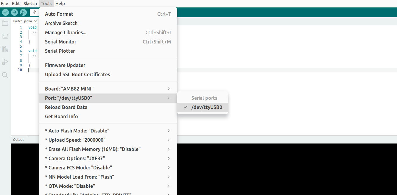
Once the board is connected, open Arduino IDE, click , and select the corresponding port from the dropdown menu, as shown below:
Note
If you are using Linux (Ubuntu) and Arduino IDE cannot detect the port connected to the board, refer to Ubuntu Environment Setup.
Project Compilation
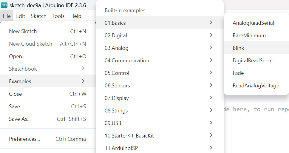
Arduino IDE provides many built-in examples that can be compiled, uploaded, and run directly on the board. Here, we use the Blink example as the first try.
Arduino Sketch Structure
Open , as shown below:
Arduino IDE opens a new window with the complete sample code, as shown below:
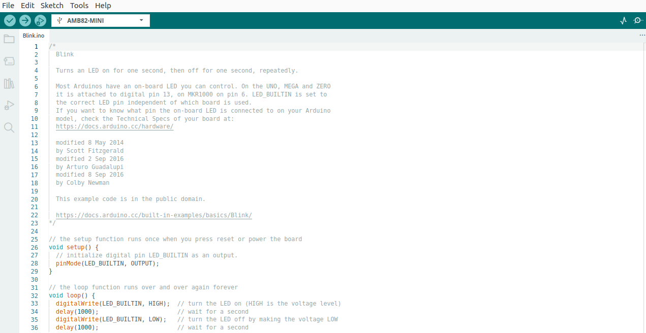
Code overview
Function |
Description |
|---|---|
setup() |
Core function used to initialize variables, pin modes, libraries, etc. Runs once after the board powers on or resets. |
loop() |
Core function — the main body of the program. Runs repeatedly after setup() completes. |
pinMode(pin, mode) |
Sets the operating mode of a specified pin. In this example, sets the |
digitalWrite(pin, value) |
Writes a value to an output pin. In this example, writes HIGH (LED on) and LOW (LED off) to the output pin. |
delay(ms) |
Pauses the program for the specified number of milliseconds before continuing. In this example, waits 1 second after each output change, producing a 1-second on / 1-second off LED blink. |
Note
The board package assigns a pin as LED_BUILTIN for each board. Refer to the board package pin definitions and the corresponding Board Guide to confirm the pin location.
For more information on Arduino API usage, refer to the official documentation: Arduino Language Reference.
Compile
Compile the sample code by clicking , as shown below:
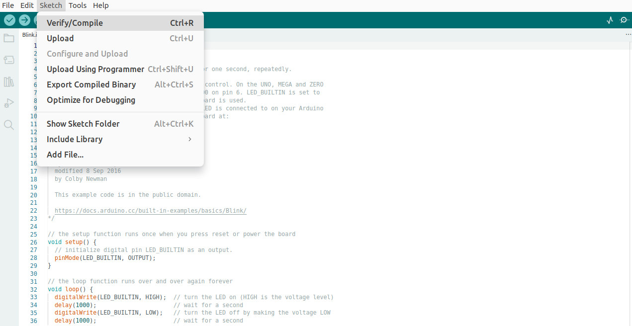
Arduino IDE displays compilation messages in the bottom area of the IDE window. When compilation is complete, the following message appears:

Firmware Download
Enter Upload Mode
Before uploading a sketch to the board, follow the steps below to enter Upload Mode.
Press and hold the UART_DOWNLOAD button.
Press and release the RESET button.
Release the UART_DOWNLOAD button.
Note
Refer to the corresponding Board Guide to locate the buttons.
Upload
Click , as shown below:
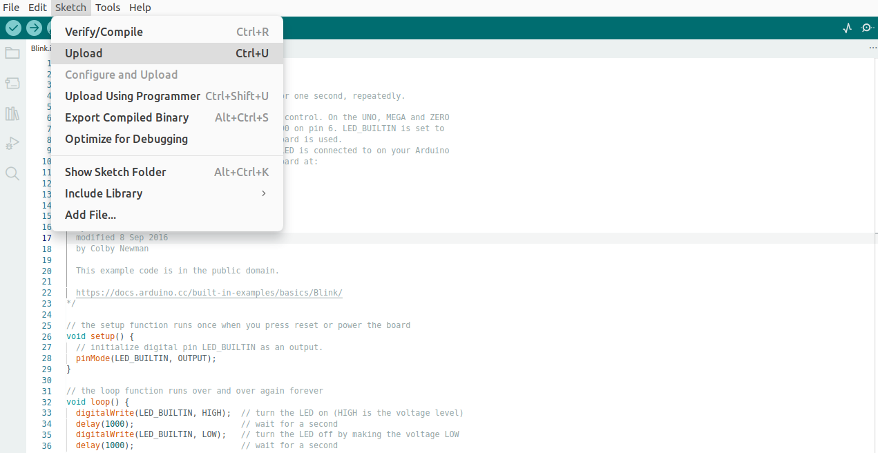
Arduino IDE will compile first, then upload.
During the upload process, the IDE displays messages. When the upload is complete, the following message appears:

Note
If Linux users encounter a Permission denied error during upload as shown below, refer to Arduino official documentation: How to upload a sketch with the Arduino IDE 2.

Run
This example makes the LED blink. Each board has a LED_BUILTIN pin connected to an LED.
AMB82-MINI has an onboard LED (LED_BUILTIN) — no external connection needed. Press and release the RESET button to see the onboard LED blink.
Log Monitoring
After uploading, open the Serial Monitor by clicking or pressing Ctrl+Shift+M.
In the baud rate dropdown at the bottom-right of the Serial Monitor, set the baud rate to match the value used in Serial.begin() in the sketch.
Press and release the RESET button to reset the board. The Serial Monitor will display the log output from the board.
Note
An incorrect baud rate will result in garbled output or no output. The default log baud rate for Ameba boards is 115200.