Ameba IoT Hub Plug and Play Examples
Ameba IoT Hub Plug and Play example shows the capability of Ameba to interact with Azure IoT Service. We provide two examples with SAS or X509 authentication where their capabilities are described in the Realtek Ameba series model file. We will elaborate on the features that Ameba supports and the usage of Azure IoT Explorer to send and receive data to and from the Ameba device.
Ameba IoT Hub Plug and Play Examples
Ameba IoT Hub Plug and Play examples are the application responsible for communication between Ameba SDK components and Azure IoT service. Basically there are two examples in our SDK, example_azure_iot_rtk_pnp_x509 and example_azure_iot_rtk_pnp_sas, which do exactly the same things except for the authentication type of connection to DPS and IoT Hub.
After Wi-Fi is connected, the example will proceed. At the beginning of the example, it will connect to your DPS and register the device to the IoT Hub. If successful, you should see your device shown on Azure IoT Explorer or provisioned on your Azure IoT Central. Next, the example will connect to the provisioned device on IoT Hub and start the plug and play process for Ameba device:
Subscribe via MQTT for commands, device twin desired properties and responses.
Initialize all components. If there are some initial values or read-only properties that you would like to initialize, you can do so at this stage.
Update reported properties for all components for the first time and then send a twin document request to check the device status on IoT Hub.
Start the telemetry thread. This thread is responsible for all component telemetry.
Start receiving the messages subscribed to from IoT Hub. Ameba device will then react to the incoming message, complete the proper operations on the corresponding component and respond to IoT Hub.
X509 and SAS example should be configured as follows:
Ameba IoT Hub Plug and Play example with X509 certificate to provision device by DPS and start plug and play process.
Select the Ameba IoT Hub Plug and Play X509 example in
example_azure_iot_entry.h
Uncomment EXAMPLE_AZURE_IOT_RTK_PNP_X509 to select the example.
Change the parameters in
example_azure_iot_rtk_pnp_x509.c
Modify ID_SCOPE to your own DPS id scope.
Modify REGISTRATION_ID to your own DPS registration id.
Modify X509CERTIFICATE to your own x509 certificate.
Modify X509PRIVATEKEY to your own x509 private key.
Make sure the certificate has the x509 v3 extension. If you are going to connect to Azure IoT Central for device provisioning, you also have to make sure the issuer and subject CN are set to the device ID in your x509 certificate.
Ameba IoT Hub Plug and Play example with SAS authentication to provision device by DPS and start plug and play process.
Select the Ameba IoT Hub Plug and Play SAS example in
example_azure_iot_entry.h
Uncomment EXAMPLE_AZURE_IOT_RTK_PNP_SAS to select the example.
Change the parameters in
example_azure_iot_rtk_pnp_sas.c
Modify ID_SCOPE to your own DPS id scope.
Modify REGISTRATION_ID to your own DPS registration id.
Modify SAS_KEY to your own SAS key.
Plug and Play Models
Realtek plug and play model files are placed on Realtek folder of Microsoft Public Repository which are defined with Digital Twins Definition Language (DTDL). The model files are divided into several components. Each component represents a feature of the device and details its telemetry, property and command to interact with Azure IoT service.
After Ameba IoT Hub PnP examples are successfully executed, you can
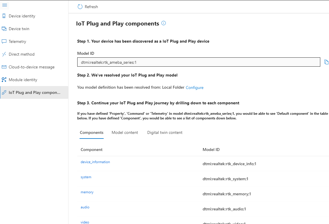
check your registered device on Azure IoT Explorer where its “IoT Plug
and Play device” column shows dtmi:realtek:rtk_ameba_series;1.

Next, you can check all components on Azure IoT Explorer and interact with Ameba.
There are four types of interfaces you can check on each component. Click on any component on the “IoT Plug and Play components” page, you will see the component details and the tabs shown as below.

[Property] The read-only property. You can check the properties in the “Properties (read-only)” tab.
[Writable Property] The writable property. You can modify writable properties in the “Properties (writable)” tab.
[Telemetry] The telemetry. You can see the telemetry messages received in the “Telemetry” tab.
[Command] The commands. You can send commands in the “Commands” tab.
Ameba Series
Ameba Series is the Ameba device model file entry. It is the default component containing all the components of the device. Our plug and play examples register the model id of this model file while connecting to DPS and IoT Hub. You will see this component page once you click on your IoT Plug and Play components page on your registered device on Azure IoT Explorer.
Audio Component defines the audio feature of the device. It only contains a support property and can be extended in the future.
[Property] audio_support: Audio support for device.
Bluetooth Component defines the Bluetooth feature of the device. It only contains a support property and can be extended in the future.
[Property] bluetooth_support: Bluetooth support for device.
Device Information Component records the information of the device containing several read-only properties. These properties should be configured by the firmware provider.
[Property] manufacturer: Company name of the device manufacturer.
[Property] model: Device model name.
[Property] fw_version: Version of the firmware on your device.
GPIO Component defines the GPIO feature of the device. In the examples, pinmux PA 12 and PB 10 are the default and can be directly used for gpio commands, but need to use gpio_set to be initialized. PB 10 is an output pin with PullNone mode and can be used as led pin. PA 12 is an input pin with PullUp mode which can be used as a button pin. You can test with these two gpio pins on Ameba device with the following commands.
Pinmux is a combination of a port number and a pin number. There are 2 types of port numbers, PA and PB. For the detailed information of a specific port number, please contact Realtek FAE for more information.
[Property] gpio_support: GPIO support for device.
[Command] gpio_set: Given a pinmux with pin mode and direction, Ameba device will set the corresponding gpio pin. If the pin number is out of range, you will get bad request response on your Azure IoT Explorer, otherwise you will get success response.
[Command] gpio_read: Read GPIO status from device. You will get 0 for pin low and 1 for pin high. If GPIO pin is not initialized (by default or by gpio_set), you will get bad request response, otherwise you will get success response.
[Command] gpio_write: Sets value to the selected output port pin. You can select OFF to set pin low and ON to set pin high. If GPIO pin is not initialized (by default or by gpio_set), you will get bad request response, otherwise you will get success response.
LCD Component defines the LCD feature of the device. It only contains a support property and will be extended in the future.
[Property] lcd_support: LCD support for device.
Memory Component defines the memory detail of the device.
[Property] total_flash: Size of flash on device. Represented with mebibyte.
[Property] total_sram: Size of sram on device. Represented with kibibyte.
[Property] total_external_ram: Size of external ram on device. Represented with mebibyte.
[Telemetry] remain_heap: Current available heap size on device. The value is represented with byte.
[Writable Property] telemetry_enable_remain_heap: Enable remain_heap option in telemetry. Set true to enable and false to disable.
[Writable Property] telemetry_interval: Interval for telemetry of Memory component. The number you set is represented with second.
System Component defines the system detail of the device.
[Property] build_info: Build information of the firmware. It is represented as an object containing 4 fields:
fw_compile_time(the time that the firmware is generated),fw_compile_by(the name of the person who builds the firmware),fw_compile_host(the host device for building firmware), andfw_compiler(compiler information). This information is auto-generated by Ameba SDK.[Property] os_info: OS information of the firmware.
[Property] processor_architecture: Processor architecture on device.
[Telemetry] device_runtime: Shows how long device has been running. Represented with seconds.
[Telemetry] cpu_usage: Shows CPU utilization of each running task. This information is directly retrieved from Ameba device OS and is represented as a single string. The message contains several task statuses where each task status is shown as
"pnp_telem\t30772\t\t3%\r\n"."pnp_telem"is the task name,"30772"is the total run time allocated to the task so far and"3%"is the percentage of the total run time that the task has used. To retrieve task status from OS, you need to enableconfigGENERATE_RUN_TIME_STATSinproject_km4\inc\FreeRTOSConfig.h.[Writable Property] telemetry_enable_device_runtime: Enable device_runtime option in telemetry. Set true to enable and false to disable.
[Writable Property] telemetry_enable_cpu_usage: Enable cpu_usage option in telemetry. Set true to enable and false to disable.
[Writable Property] telemetry_interval: Interval for telemetry of System component. The number you set is represented with second. The above two telemetry of System will be set to the same interval.
[Command] reboot: System reboots after a given time. We will leave 5 seconds to reboot the device to make sure the command response is correctly sent from the device. If the time you set is less than 5 seconds from now or even you set a time that has already passed, the device will reboot in 5 seconds.
[Command] switch_to_upgraded_image: Switch to OTA upgraded firmware and reboot the device in 5 seconds. OTA process should be done before switching firmware and make sure the OTA firmware can connect to IoT Hub and function well.
[Command] switch_to_default_image: Switch back to default firmware and reboot the device in 5 seconds.
Video Component defines the video feature of the device. It only contains a support property and will be extended in the future.
[Property] video_support: Video support for device.
Wireless Component defines the Wi-Fi feature of the device.
[Property] wireless_support: Wireless support for device.
[Property] specification: Wireless specification.
[Telemetry] wifi_info: The telemetry message that shows current Wi-Fi connection information. It is represented as an object containing the station mode connection information and station mode interface configuration.
Station mode connection information: ssid (SSID of the connected AP), channel (connected channel to AP), security (security type of connecting AP, one of OPEN/WEP/TKIP/AES/UNKNOWN), password (password of connecting AP, empty if open mode).
Station mode interface configuration: mac (mac address of device station mode interface), ip (assigned IP address), gw (gateway), msk (network mask).
[Writable Property] telemetry_enable_wifi_info: Enable wifi_info option in telemetry. Set true to enable and false to disable.
[Writable Property] telemetry_interval: Interval for telemetry of Wireless component. The number you set is represented with second.
[Command] wifi_connect: Connect to specified AP with your given ssid and password. It will respond with success and start a Wi-Fi connection thread to connect to the specified AP after 5 seconds.
[Command] wifi_scan: Scan for network access points around the device. You can specify the channels you would like to scan by providing the numbers of channels as array elements. Leave blank to scan all channels by default. Note that it is possible to take a longer time to search for the access points and cause response timeout if you scan for all channels. The response contains at most 5 objects where each object records: idx (index of scanned AP, starting from 1), bss_type (Adhoc or Infra), mac (mac address of AP), signal_strength (signal strength in db), channel (channel of AP), wps_type (one of DEFAULT/USER_SPECIFIED/MACHINE_SPECIFIED/REKEY/PUSHBUTTON/REGISTRAR_SPECIFIED/NONE/WSC/Unknown), security (one of Open/WEP/WPA TKIP/WPA AES/WPA2 AES/WPA2 TKIP/WPA2 Mixed/WPA/WPA2 AES/WPA3-SAE AES/Unknown), ssid (SSID of scanned AP).
[Command] ota: Over-the-Air firmware update via Wi-Fi. The OTA image should be placed on a local server and the device will download the upgraded image from the local server. Provide
"ip_address"as IP of local server and"port"as port of local server. After OTA is done, you can use"switch_to_upgraded_image"and"switch_to_default_image"commands in System component to switch firmware. For the details of the OTA process and the OTA image generation, please refer to Ameba online document or contact Realtek FAE for further information.[Command] ping: Ping for specified host. Provide host_address (valid IP like 127.0.0.1), number (number of pings, defaults to 4, max 20), and buffer_size (payload size, default 32 Byte). The ping response contains: info (ping info you provided), content (ping results as array elements), and result (conclusion of the ping process).