Zephyr Development
DTS Introduction
Zephyr Configuration System
Zephyr compilation is divided into two phases:
Configuration phase: Execute cmake to process DTS and Kconfig
DTS is converted to
build/zephyr/include/generated/zephyr/devicetree_generated.hKconfig is converted to:
build/zephyr/include/generated/zephyr/autoconf.h
Build phase: Execute make or ninja tools to generate firmware
Refer to the following diagram for the main flow of the configuration phase:

DTS Configuration
DTS Basic Syntax
DTS consists of nodes, and each node contains several properties or child nodes.
Basic node form:
node_label:node_name@unit-address{...}Basic property form:
prop_name = value;, which is a key-value pair (except for boolean type, which has only an identifier; its presence indicatesTrue)
The following diagram illustrates the structure of a simple DTS file:

A Real Hardware Example
Assume the following hardware structure:

The DTS structure can be used to describe this hardware:

Write the DTS file as follows:
/dts-v1/;

/ {
  clocks {
    fixed_clk: fixed_clk_node {
    };

    main_clk: main_clk_node@41008000 {
    };
  };

  soc {
    usb: usb@40140000 {
      clocks = <&fixed_clk>;
    };

    uart0: serial@4100c000 {
      clocks = <&main_clk UART0_CLK>;
    };
    spi0: spi@40124000 {
      clocks = <&main_clk SPI0_CLK>;
    };
  }
};
unit-address
The unit-address in a node can be omitted; when present, the corresponding node must contain the reg property, and its first element value must equal the unit-address
Attention
unit-address can serve as part of the node identifier, meaning two nodes with the same node_name but different unit-address values are allowed. However, if neither node has a unit-address, an error will occur.
Important Properties
reg
It is a sequence of
(address, size)pairs, each describing a register block. The specific meaning varies by device. For example:UART device:
reg = <0x100000 0x100>, <0x200000 0x100>;, has two register blocksCPU:
reg = <0>typically represents the CPU number in multi-CPU systems, consistent withcpu@0
The bit widths of
addressandsizein reg are described by theaddress-cellsandsize-cellsproperties in the parent node of the node they belong to. For example:/ { clocks { #address-cells = <2>; #size-cells = <1>; main_clk: main_clk_node@41008000 { compatible = "realtek,ameba-rcc"; reg = <0x12345678 0xABCD0000 0x400>; }; }; }
- In the
clocknode,#address-cellsand#size-cellsrespectively constrain theregin its direct child node (main_clk): addressconsists of a 32-bit cellsizeconsists of a 32-bit cell
- In the
When
#size-cellsis 0, thesizepart is not needed inreg
compatible
The
compatibleproperty consists of one or more strings, each corresponding to a DTS Binding file that defines the programming model for nodes containing this propertyNodes using
compatiblemust also comply with these programming modelsThe binding method between
compatiblestrings and DTS Binding files is: the compatible field value in the DTS Binding file equals the string, so DTS scripts can automatically find the corresponding DTS Binding file through thecompatibleproperty valueWhen
compatiblehas multiple values, the build script matches from left to right until it finds the first matching DTS Binding file; others are ignored
DTS Organization in Zephyr
In Zephyr, a board’s DTS description is completed by multiple dts(i) files
These files come from three layers divided by different abstraction levels:
Arch layer: Highest level of abstraction, defines hardware descriptions related to CPU instruction set architecture
SoC layer: Medium level of abstraction, typically hardware descriptions for a specific series provided by a vendor, including peripherals, clock control, interrupts, pins, etc.
Board layer: Lowest level of abstraction, corresponds to a specific hardware entity, specifically describing onboard peripherals configuration, pin mappings, etc.
The board layer DTS is the entry point for processing scripts, usually including the SoC layer DTS, which in turn includes the Arch layer DTS
The DTS processing script ultimately generates a complete dts (build/zephyr/zephyr.dts)
Refer to the following diagram for DTS processing inputs and outputs:

DTS Binding
Note
Functionality:
DTS binding files define the programming model for DTS nodes that reference them, which can be simply understood as specifications or constraints, such as node property requirements (which properties exist, property types, allowed values, etc.), child node bindings, bus information, etc.
DTS binding supports referencing other files through include to achieve reuse functionality
DTS binding file location: By default, look in zephyr/dts/bindings (generally recommended), or:
- CMakeLists.txt: list(APPEND DTS_ROOT /path/to/your/dts)
- west command parameter: -DDTS_ROOT=/path/to/your/dts
DTS Binding Basic Syntax
DTS binding is in YAML format. The following diagram introduces each field with examples:

The following details some of the more important fields:
include
The included binding file will be merged with the current binding file to form a complete binding file
If a field value in the current binding file differs from the same field in its include, an error will occur, except for the
requirefield in propertiesYou can also selectively import some properties from the include file. Refer to the following example:
include:
  - name: foo.yaml
    property-allowlist:  //Import including some specific properties
      - i-want-this-one
      - and-this-one
  - name: bar.yaml
    property-blocklist: //Import excluding some specific properties
      - do-not-include-this-one
      - or-this-one
compatible
Primarily used to match the
compatibleproperty in DTS files to bind the binding file to the corresponding nodeTypically takes the form:
<vender>,<device>
properties
Primarily used to add descriptions and constraints to properties in DTS nodes. The complete syntax is as follows:
properties:
    <property name>:
      required: <true | false>
      type: <string | int | boolean | array | uint8-array | string-array |
            phandle | phandles | phandle-array | path | compound>
      deprecated: <true | false>
      default: <default>
      description: <description of the property>
      enum:
        - <item1>
        - <item2>
        ...
        - <itemN>
      const: <string | int>
required: Set to true indicates that the property must be declared in the corresponding node, otherwise the script will report an errortype: Describes the property type. See DTS Property Data Types for detailsdeprecated: Set to true indicates that the property is deprecated; the tool will report a warning during compilationdefault: Sets a default value for the propertyenum: A list specifying the allowed values for the property; if a value outside this list is set in the node, an error will occurconst: Indicates that the property is a constant
Specifier Cell
The function of Specifier cell can be understood as specifying the init parameters for a device. They can pass parameters for initialization when the device is instantiated (phandle reference). The following example explains how it works. Assume a DTS file as follows:
/ {
  soc {
    dma: dma@40110000 {
      compatible = "realtek,ameba-gdma";
      reg = <0x40110000 0x3C0>;
      #dma-cells = <3>;
    };

    i2c0: i2c0@41108000 {
      compatible = "realtek,ameba-i2c";
      reg = <0x41108000 0x100>;
      dmas = <&dma 4 22 0>,
             <&dma 5 21 0>;
      dma-names = "rx", "tx";
    };
  };
}
Focus on the hardware logic defined in it:
The SOC node contains a dma child node (line 3) and an i2c0 child node (line 9). The i2c0 device uses two dma instances (lines 12, 13) named rx/tx respectively (line 14).
The
dmasproperty is of phandle-array type, containing two dma instances, each initialized using three parameters (4 22 0and5 21 0).The specification for these three initialization parameters is defined through the Specifier cell field in the binding file. See the binding file
realtek,ameba-gdma.yaml:compatible: "realtek,ameba-gdma" include: dma-controller.yaml properties: "#dma-cells": const: 3 dma-cells: - channel //Select channel for data transmitting - slot //Handshake interface index, ref to ameba_gdma.h - config //include direction/addr inc/data width/msize
Where:
The
"#dma-cells"property inpropertyspecifies the number of parametersdma-cellsdescribes the names of these three parameters, which can be accessed in C code by their corresponding names
Accessing these parameters in C code:
#define I2C_DMA_CHANNEL_INIT(index, dir)                                 \
 .dma_dev = AMEBA_DT_INST_DMA_CTLR(index, dir),                         \
 .dma_channel = DT_INST_DMAS_CELL_BY_NAME(index, dir, channel),         \
 .dma_cfg = AMEBA_DMA_CONFIG(index, dir, 1, i2c_ameba_dma_##dir##_cb),
Where:
The
indexparameter is the index for iterating through multiple i2c instancesdiris the index for accessing dmas; here dir can berxortxchannelcorresponds to the first parameter described indma-cellsin the binding fileSo the final value of
.dma_channelhere is 4 or 5
Attention
The dmas property name in the i2c0 node in DTS is fixed; its singular form dma must match the name before the - in the Specifier cell in the binding file
DTS Operation Guide
To be added
Extended Reading
DTS Property Data Types
Property type |
How to write |
Example |
|---|---|---|
string |
Double quoted |
|
int |
between angle brackets ( |
|
boolean |
for |
|
array |
between angle brackets ( |
|
uint8-array |
in hexadecimal without leading |
|
string-array |
separated by commas |
|
phandle |
between angle brackets ( |
|
phandles |
between angle brackets ( |
|
phandle-array |
between angle brackets ( |
|
NVIC Introduction
Interrupt Information
DTS Configuration
Set the driver’s interrupt properties as shown in the highlighted lines below. The interrupts property takes two parameters: the first is the interrupt number, and the second is the interrupt priority.
nvic: interrupt-controller@e000e100 {
   #address-cells = < 0x1 >;
   compatible = "arm,v8.1m-nvic";
   reg = < 0xe000e100 0xc00 >;
   interrupt-controller;
   #interrupt-cells = < 0x2 >;
   arm,num-irq-priority-bits = < 0x3 >;
   phandle = < 0x1 >;
};
timer0: counter@40819000 {
   compatible = "realtek,ameba-counter";
   reg = <0x40819000 0x30>;
   clocks = <&rcc AMEBA_LTIM0_CLK>;
   interrupts = <7 0>;
   clock-frequency = <32768>;
   status = "disabled";
};
Getting Interrupt Properties
The macros for retrieving information from DTS are defined in the file zephyr/include/zephyr/devicetree.h.
Driver code needs to use the interrupt number when registering an interrupt. Here’s how to get it:
DT_INST_IRQN
#define DT_INST_IRQN(inst) DT_IRQN(DT_DRV_INST(inst))
Get the interrupt number for the DT_DRV_COMPAT device. Parameter description:
- inst:
Device instance number
When registering an interrupt in driver code, use macros to retrieve the priority from DTS. Here’s how:
DT_INST_IRQ
#define DT_INST_IRQ(inst, cell) DT_INST_IRQ_BY_IDX(inst, 0, cell)
Get the value of the DT_DRV_COMPAT interrupt specifier. Parameter description:
- inst:
Instance number
- cell:
Cell name specifier
DT_INST_IRQ_BY_NAME
#define DT_INST_IRQ_BY_NAME(inst, name, cell) \
    DT_IRQ_BY_NAME(DT_DRV_INST(inst), name, cell)
Get the value of the DT_DRV_COMPAT interrupt specifier by name. Parameter description:
- inst:
Instance number
- name:
Name of the interrupt specifier, using lowercase letters and underscores.
- cell:
Cell name specifier
DT_INST_IRQ_BY_IDX
#define DT_INST_IRQ_BY_IDX(inst, idx, cell) \
    DT_IRQ_BY_IDX(DT_DRV_INST(inst), idx, cell)
Get the value of the DT_DRV_COMPAT interrupt specifier by index. Parameter description:
- inst:
Instance number
- idx:
Logical index of the interrupt specifier array
- cell:
Cell name specifier
Interrupt Priority Explanation
In the DTS, arm,num-irq-priority-bits = < 0x3 > is configured, meaning the priority register has three bits with a maximum of 8 priority levels.
Priority-related macros have different implementations for different architectures. The Cortex-M implementation is in the file zephyr/include/zephyr/arch/arm/cortex_m/exception.h, as shown below:
#if defined(CONFIG_CPU_CORTEX_M_HAS_PROGRAMMABLE_FAULT_PRIOS)
#define _EXCEPTION_RESERVED_PRIO 1
#else
#define _EXCEPTION_RESERVED_PRIO 0
#endif
#define _EXC_FAULT_PRIO             0
#define _EXC_ZERO_LATENCY_IRQS_PRIO 0
#define _EXC_SVC_PRIO               COND_CODE_1(CONFIG_ZERO_LATENCY_IRQS,       \
                (CONFIG_ZERO_LATENCY_LEVELS), (0))
#define _IRQ_PRIO_OFFSET            (_EXCEPTION_RESERVED_PRIO + _EXC_SVC_PRIO)
#define IRQ_PRIO_LOWEST             (BIT(NUM_IRQ_PRIO_BITS) - (_IRQ_PRIO_OFFSET) - 1)
#define _EXC_IRQ_DEFAULT_PRIO Z_EXC_PRIO(_IRQ_PRIO_OFFSET)
/* Use lowest possible priority level for PendSV */
#define _EXC_PENDSV_PRIO      0xff
#define _EXC_PENDSV_PRIO_MASK Z_EXC_PRIO(_EXC_PENDSV_PRIO)
Interrupt Registration
There are two types of ISRs: normal ISR and direct ISR, with different registration methods. Normal ISRs have two registration methods: compile-time registration and runtime registration, depending on whether parameters are known at compile time; Direct ISRs require declaration before registration. You can refer to Interrupt Vector Table Query to help understand the difference between the two ISR registration methods.
Normal ISR
Compile-time Registration
Use the IRQ_CONNECT macro for compile-time ISR registration. Compile-time registration is used when all parameters are already determined.
The related implementation is in the file include/irq.h, as shown below:
#define IRQ_CONNECT(irq_p, priority_p, isr_p, isr_param_p, flags_p) \
    ARCH_IRQ_CONNECT(irq_p, priority_p, isr_p, isr_param_p, flags_p)
Parameter description:
- irq_p:
Interrupt number
- priority_p:
Interrupt priority
- isr_p:
Address of the interrupt service routine
- isr_param_p:
Parameter passed to the interrupt service routine
- flags_p:
Architecture-specific IRQ configuration flags
Different architectures have different implementations. The ARM architecture implementation is in the file zephyr/include/zephyr/arch/arm/irq.h, as shown below:
#define ARCH_IRQ_CONNECT(irq_p, priority_p, isr_p, isr_param_p, flags_p) \
{ \
    BUILD_ASSERT(IS_ENABLED(CONFIG_ZERO_LATENCY_IRQS) || !(flags_p & IRQ_ZERO_LATENCY), \
            "ZLI interrupt registered but feature is disabled"); \
    _CHECK_PRIO(priority_p, flags_p) \
    Z_ISR_DECLARE(irq_p, 0, isr_p, isr_param_p); \
    z_arm_irq_priority_set(irq_p, priority_p, flags_p); \
}
#define Z_ISR_DECLARE(irq, flags, func, param) \
    static Z_DECL_ALIGN(struct _isr_list) Z_GENERIC_SECTION(.intList) \
        __used _MK_ISR_NAME(func, __COUNTER__) = \
            {irq, flags, (void *)&func, (const void *)param}
Note
Z_ISR_DECLARE generates a struct _isr_list structure variable placed in the .intList section. The structure variable contains the interrupt number irq,
flags, interrupt function func, and the parameter param passed to the interrupt function.
The struct _isr_list structure is defined as follows:
struct _isr_list {
    /** IRQ line number */
    int32_t irq;
    /** Flags for this IRQ, see ISR_FLAG_* definitions */
    int32_t flags;
    /** ISR to call */
    void *func;
    /** Parameter for non-direct IRQs */
    const void *param;
};
If the passed function is uart_isr and this is the 5th call to Z_ISR_DECLARE, then the expanded content of Z_ISR_DECLARE would be:
static  __aligned(__alignof(struct _isr_list))struct _isr_list  __attribute__((section(".intList")))
    __used __isr_uart_isr_irq_5 = {
        irq,
        0,
        uart_isr,
        param}
The structure variable __isr_uart_isr_irq_5 will be placed in .intList.
Runtime Registration
Since the IRQ_CONNECT macro requires all its parameters to be known at compile time, this may not be acceptable in some cases. You can also use irq_connect_dynamic() to install interrupts at runtime.
The related implementation is in the file zephyr/include/irq.h, as shown below:
static inline int
irq_connect_dynamic(unsigned int irq, unsigned int priority,
            void (*routine)(const void *parameter),
            const void *parameter, uint32_t flags)
{
    return arch_irq_connect_dynamic(irq, priority, routine, parameter,
                    flags);
}
Parameter description:
- irq:
Interrupt number
- priority:
Interrupt priority
- routine:
Address of the interrupt service routine
- parameter:
Parameter passed to the interrupt service routine
- flags:
Architecture-specific IRQ configuration flags
The Cortex-M architecture function implementation is in the file zephyr/arch/arm/core/cortex_m/irq_manage.c, as shown below:
int arch_irq_connect_dynamic(unsigned int irq, unsigned int priority,
                 void (*routine)(const void *parameter), const void *parameter,
                 uint32_t flags)
{
    z_isr_install(irq, routine, parameter);
    z_arm_irq_priority_set(irq, priority, flags);
    return irq;
}
z_isr_install() registers the interrupt as follows, mainly by dynamically modifying _sw_isr_table:
void __weak z_isr_install(unsigned int irq, void (*routine)(const void *),
             const void *param)
{
    unsigned int table_idx;
    table_idx = z_get_sw_isr_table_idx(irq);
    /* If dynamic IRQs are enabled, then the _sw_isr_table is in RAM and
     * can be modified
     */
    _sw_isr_table[table_idx].arg = param;
    _sw_isr_table[table_idx].isr = routine;
}
Direct ISR
Declaration
Unlike normal ISRs, direct ISR functions need to be declared first. The related macros are in the file include/irq.h, with the code below:
#define ISR_DIRECT_DECLARE(name) ARCH_ISR_DIRECT_DECLARE(name)
#define ISR_DIRECT_HEADER() ARCH_ISR_DIRECT_HEADER()
#define ISR_DIRECT_FOOTER(check_reschedule) \
    ARCH_ISR_DIRECT_FOOTER(check_reschedule)
Different architectures have different implementations. The ARM architecture implementation is in the file zephyr/include/zephyr/arch/arm/irq.h, with the code below:
#define ARCH_ISR_DIRECT_DECLARE(name) \
    static inline int name##_body(void); \
    ARCH_ISR_DIAG_OFF \
    __attribute__ ((interrupt ("IRQ"))) void name(void) \
    { \
        int check_reschedule; \
        ISR_DIRECT_HEADER(); \
        check_reschedule = name##_body(); \
        ISR_DIRECT_FOOTER(check_reschedule); \
    } \
    ARCH_ISR_DIAG_ON \
    static inline int name##_body(void)

#define ARCH_ISR_DIRECT_HEADER() arch_isr_direct_header()
static inline void arch_isr_direct_header(void)
{
#ifdef CONFIG_TRACING_ISR
    sys_trace_isr_enter();
#endif
}

#define ARCH_ISR_DIRECT_FOOTER(swap) arch_isr_direct_footer(swap)
static inline void arch_isr_direct_footer(int maybe_swap)
{
#ifdef CONFIG_TRACING_ISR
    sys_trace_isr_exit();
#endif
    if (maybe_swap != 0) {
        z_arm_int_exit();
    }
}
The direct ISR declaration mainly adds a header and footer around the original interrupt service function, providing some common operations for all direct ISRs.
Note
The kernel allows interrupt handlers (ISRs) to be installed directly into the vector table to minimize interrupt latency as much as possible. This allows ISRs to be called directly without going through the software interrupt table.
However, some kernel work is still required when exiting the ISR, such as context switching. ISRs connected to the software interrupt table perform this operation automatically through the wrapper _isr_wrapper,
while direct ISRs connected to the hardware vector table add this operation through ARCH_ISR_DIRECT_FOOTER in ISR_DIRECT_DECLARE.
Registration
Direct ISRs are registered through IRQ_DIRECT_CONNECT. The macro is defined in the file include/irq.h, as shown below:
#define IRQ_DIRECT_CONNECT(irq_p, priority_p, isr_p, flags_p) \
    ARCH_IRQ_DIRECT_CONNECT(irq_p, priority_p, isr_p, flags_p)
Parameter description:
- irq_p:
Interrupt number
- priority_p:
Interrupt priority
- isr_p:
Address of the interrupt service routine
- flags_p:
Architecture-specific IRQ configuration flags
Note
IRQ_DIRECT_CONNECT has one fewer parameter than IRQ_CONNECT: isr_param_p. Direct ISRs do not need parameters and can jump directly to execution in the hardware vector table.
Different architectures have different implementations. The ARM architecture implementation is in the file zephyr/include/zephyr/arch/arm/irq.h, as shown below:
#define ARCH_IRQ_DIRECT_CONNECT(irq_p, priority_p, isr_p, flags_p) \
{ \
    BUILD_ASSERT(IS_ENABLED(CONFIG_ZERO_LATENCY_IRQS) || !(flags_p & IRQ_ZERO_LATENCY), \
         "ZLI interrupt registered but feature is disabled"); \
    _CHECK_PRIO(priority_p, flags_p) \
    Z_ISR_DECLARE_DIRECT(irq_p, ISR_FLAG_DIRECT, isr_p); \
    z_arm_irq_priority_set(irq_p, priority_p, flags_p); \
}
#define Z_ISR_DECLARE_DIRECT(irq, flags, func) \
    Z_ISR_DECLARE(irq, ISR_FLAG_DIRECT | (flags), func, NULL)
Note
The direct ISR registration macro also calls Z_ISR_DECLARE, which is very similar to normal ISR registration overall. The only difference is that flag = ISR_FLAG_DIRECT, meaning that for direct ISRs, a struct _isr_list
structure variable is still generated and placed in .intList.
Enable/Disable Interrupt
Enable Interrupt
After interrupt registration is complete, you need to enable the interrupt for it to respond normally. The interrupt enable function is as follows:
#define irq_enable(irq) arch_irq_enable(irq)
Parameter description:
- irq:
Interrupt number
Disable Interrupt
After enabling an interrupt, if you want it to stop responding, you can disable the interrupt. The interrupt disable function is as follows:
#define irq_disable(irq) arch_irq_disable(irq)
Parameter description:
- irq:
Interrupt number
Interrupt Response
Interrupt Vector Table
The Zephyr interrupt vector table is divided into three parts, as shown in the diagram below:

exc_vector_table contains the first 16 exception vectors, _irq_vector_table is the hardware interrupt vector table, and _sw_isr_table is the software interrupt vector table. The representation is as follows:
/*System exception loading*/
SECTION_SUBSEC_FUNC(exc_vector_table,_vector_table_section,_vector_table)
    .word z_main_stack + CONFIG_MAIN_STACK_SIZE
    .word z_arm_reset
    .word z_arm_nmi
    .word z_arm_hard_fault
    .word z_arm_mpu_fault
    .word z_arm_bus_fault
    .word z_arm_usage_fault
    .word z_arm_secure_fault
    .word 0
    .word 0
    .word 0
    .word z_arm_svc
    .word z_arm_debug_monitor
    .word 0
    .word z_arm_pendsv
    .word sys_clock_isr
/*Hardware interrupt vector table*/
uintptr_t __irq_vector_table _irq_vector_table[80] = {
        ((uintptr_t)&_isr_wrapper),
        ((uintptr_t)&_isr_wrapper),
        ((uintptr_t)&_isr_wrapper),
        ((uintptr_t)&direct_isr_pwm1),
        ((uintptr_t)&_isr_wrapper),
        ((uintptr_t)&_isr_wrapper),
    ...
}
/*Software interrupt vector table*/
struct _isr_table_entry __sw_isr_table _sw_isr_table[80] = {
        {(const void *)0x0, (ISR)z_irq_spurious}, /* 0 */
        {(const void *)0x0, (ISR)z_irq_spurious}, /* 1 */
        {(const void *)0x0, (ISR)z_irq_spurious}, /* 2 */
        {(const void *)0x0, (ISR)z_irq_spurious}, /* 3 */
        {(const void *)0x0, (ISR)z_irq_spurious}, /* 4 */
        {(const void *)0x40815000, (ISR)0x2027de1}, /* 5 */
    ...
}
Note
The hardware interrupt vector table irq_vector_table and software interrupt vector table sw_isr_table are initially empty. During compilation, a new interrupt vector table is generated based on compile-time registered interrupts,
and normal ISRs are added to the software interrupt table at runtime.
Query Interrupt Vector Table
When an interrupt occurs, the hardware interrupt vector table _irq_vector_table is queried. Possible scenarios are:
If it’s not
_isr_wrapper(), it’s a direct interrupt, and the ISR is entered directly.If it is
_isr_wrapper(), it’s a normal interrupt. Enter_isr_wrapper()and look up_sw_isr_tableto find the corresponding ISR. If it’s notz_irq_spurious(), it will execute normally.If it’s a normal interrupt but the ISR found in
_sw_isr_tableisz_irq_spurious(), it means the interrupt is not registered, and an error will be reported.
Note
z_irq_spurious() is installed in all _sw_isr_table slots at startup. It throws an error when called.
The query diagram is as follows:

_isr_wrapper() has different implementations for different architectures. The Cortex-M implementation is in the file zephyr/arch/arm/core/cortex_m/isr_wrapper.c, as shown below:
void _isr_wrapper(void)
{
#ifdef CONFIG_TRACING_ISR
    sys_trace_isr_enter();
#endif /* CONFIG_TRACING_ISR */
    int32_t irq_number = __get_IPSR();
    irq_number -= 16;

    struct _isr_table_entry *entry = &_sw_isr_table[irq_number];
    (entry->isr)(entry->arg);

#if defined(CONFIG_ARM_CUSTOM_INTERRUPT_CONTROLLER)
    z_soc_irq_eoi(irq_number);
#endif
#ifdef CONFIG_TRACING_ISR
    sys_trace_isr_exit();
#endif /* CONFIG_TRACING_ISR */
    z_arm_exc_exit();
}
In _isr_wrapper(), you can uniformly perform some common operations, such as enabling/disabling trace and kernel cleanup before exception handler exit,
similar to ISR_DIRECT_HEADER() and ISR_DIRECT_FOOTER() added when declaring direct interrupts.
_sw_isr_table does not map exceptions, only interrupts. Since the first 16 interrupt numbers are already used by system exceptions, the interrupt number read from the IPSR must be reduced by 16.
Other Related Information
Multi-level Interrupts
Hardware platforms can support more interrupt lines than native interrupt lines by using one or more nested interrupt controllers. Hardware interrupt sources are merged into a single line, then routed to the parent controller.
If nested interrupt controllers are supported, the CONFIG_MULTI_LEVEL_INTERRUPTS option should be enabled, and CONFIG_2ND_LEVEL_INTERRUPTS and CONFIG_3RD_LEVEL_INTERRUPTS options should be configured according to the hardware architecture.
An example of multi-level interrupt DTS configuration is as follows:
test_cpu_intc: interrupt-controller  {
        compatible = "vnd,cpu-intc";
        #interrupt-cells = < 0x01 >;
        interrupt-controller;
};
test_l1_irq: interrupt-controller@bbbbcccc  {
        compatible = "vnd,intc";
        reg = <0xbbbbcccc 0x1000>;
        interrupt-controller;
        #interrupt-cells = <2>;
        interrupts = <11 0>;
        interrupt-parent = <&test_cpu_intc>;
};
test_l2_irq: interrupt-controller@bbbccccc  {
    compatible = "vnd,intc";
    reg = <0xbbbccccc 0x1000>;
    interrupt-controller;
    #interrupt-cells = <2>;
    interrupts = <12 0>;
    interrupt-parent = <&test_l1_irq>;
};
test_l1_irq_inc: interrupt-controller@bbbbdccc  {
    compatible = "vnd,intc";
    reg = <0xbbbbdccc 0x10>;
    interrupt-controller;
    #interrupt-cells = <2>;
    interrupts = <12 0>; /* +1 */
    interrupt-parent = <&test_cpu_intc>;
};
The system allocates a unique 32-bit interrupt number that contains information for selecting and calling the correct interrupt service routine (ISR). Each interrupt level is allocated one byte (configurable) in this 32-bit interrupt number. This architecture can support up to four interrupt levels, as shown below (three interrupt levels shown here):
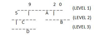
“-” represents interrupt lines, numbered starting from 0 (rightmost).
Level 1 has 12 interrupt lines, two of which (lines 2 and 9) are connected to nested controllers, and a device “A” is connected on line 4.
One of the level 2 controller’s interrupt line 5 is connected to a level 3 nested controller, and a device “C” is connected on line 3.
Another level 2 controller has no nested controller, but a device “B” is connected on line 2.
The level 3 controller has a device “D” connected on line 2.
Starting from the low bits, each interrupt level occupies one byte. Taking the four interrupts shown above as examples, labeled A, B, C, and D, their interrupt numbers are represented as follows:
A -> 0x00000004
B -> 0x00000302
C -> 0x00000409
D -> 0x00030609
Interrupt Lock/Unlock
You can use irq_lock() and irq_unlock(key) to enable and disable interrupt lock state, creating critical section protection. When interrupt lock is enabled,
interrupts with priority values greater than or equal to _EXC_IRQ_DEFAULT_PRIO will be masked. The function implementation is as follows:
#define irq_lock() arch_irq_lock()
#define irq_unlock(key) arch_irq_unlock(key)

static ALWAYS_INLINE unsigned int arch_irq_lock(void)
{
    unsigned int key;
#if defined(CONFIG_ARMV7_M_ARMV8_M_MAINLINE)
    key = __get_BASEPRI();
    __set_BASEPRI_MAX(_EXC_IRQ_DEFAULT_PRIO);
    __ISB();
#endif
    return key;
}
static ALWAYS_INLINE void arch_irq_unlock(unsigned int key)
{
#if defined(CONFIG_ARMV7_M_ARMV8_M_MAINLINE)
    __set_BASEPRI(key);
    __ISB();
#endif
}
Zero Latency Interrupts
Blocking interrupts by applying IRQ locks may increase observed interrupt latency. However, for some low-latency use cases, higher interrupt latency may be unacceptable.
The kernel addresses such use cases by allowing interrupts with strict latency constraints to execute at a priority that won’t be blocked by interrupt locks.
These interrupts are defined as zero-latency interrupts. Support for zero-latency interrupts requires enabling CONFIG_ZERO_LATENCY_IRQS.
Any interrupt configured as zero-latency must also be declared as a direct ISR (and must not use ISR_DIRECT_PM in it),
because normal ISRs interact with the kernel. Additionally, the flag IRQ_ZERO_LATENCY must be passed to the IRQ_DIRECT_CONNECT macro
to configure the specific interrupt as zero-latency. On some architectures, zero-latency interrupt ISRs can be declared as both direct interrupts and dynamic interrupts.
The implementation of zero-latency interrupts mainly relies on the interrupt lock priority being lower than or equal to _EXC_IRQ_DEFAULT_PRIO. Setting the zero-latency interrupt priority
higher than _EXC_IRQ_DEFAULT_PRIO enables zero-latency interrupts. The implementation of related macros in the code is as follows:
/*If zero-latency interrupts are configured, the _EXC_IRQ_DEFAULT_PRIO used during lock increases by the priority offset reserved for zero-latency interrupts*/
#define _EXC_SVC_PRIO               COND_CODE_1(CONFIG_ZERO_LATENCY_IRQS,       \
                 (CONFIG_ZERO_LATENCY_LEVELS), (0))
#define _IRQ_PRIO_OFFSET            (_EXCEPTION_RESERVED_PRIO + _EXC_SVC_PRIO)

#define _EXC_IRQ_DEFAULT_PRIO Z_EXC_PRIO(_IRQ_PRIO_OFFSET)
Note
To reduce flash access latency, consider migrating the ISR and all its related symbols to RAM.
Configuration Notes
- GEN_ISR_TABLES:
Generate _isr_table
- GEN_IRQ_VECTOR_TABLE:
Generate _irq_vector_table
- CONFIG_GEN_SW_ISR_TABLE:
Generate _sw_isr_table
- CONFIG_ISR_TABLES_LOCAL_DECLARATION:
Creates table entries locally at the location where the IRQ_CONNECT macro is called, then uses linker scripts to position them in the correct location in memory
- CONFIG_LTO:
Enable link-time optimization
- CONFIG_IRQ_VECTOR_TABLE_JUMP_BY_ADDRESS:
The interrupt vector table performs jumps directly by ISR address
- CONFIG_IRQ_VECTOR_TABLE_JUMP_BY_CODE:
The interrupt vector table performs jumps via jump instructions
- CONFIG_NUM_IRQS:
Configure the number of interrupts
- CONFIG_SHARED_INTERRUPTS:
Enable shared interrupts
- CONFIG_SHARED_IRQ_MAX_NUM_CLIENTS:
Maximum number of shared interrupt clients
- CONFIG_MULTI_LEVEL_INTERRUPTS:
Enable multi-level interrupts
File System Introduction
File System Introduction
Zephyr File System is an important component of its service layer.
Zephyr supports multiple file system types (FatFS, LittleFS, Ext2), allowing flexible selection based on application requirements. Its design follows modular principles, enabling developers to customize through Kconfig configuration tools.
Zephyr supports multiple file system types working simultaneously, configured by FILE_SYSTEM_MAX_TYPES in Kconfig, with a default value of 2.
Zephyr allows applications to mount multiple file systems (littlefs or fatfs) at different mount points (e.g., /lfs and /fatfs), with each mount point independently maintaining file system instantiation, mounting, and file operations.
The directories and files related to the file system are shown below:
nuwa $
├── modules
│   ├── fs              # third party github
│   │   ├── fatfs
│   │   └── littlefs
└── zephyr
    ├── include
    │   ├── zephyr
    │   │   ├── fs      # file system API
    ├── modules
    │   ├── fatfs       # fatfs adapter layer
    │   ├── littlefs    # littlefs adapter layer
    ├── subsys
    │   ├── fs          # zephyr file system subsystem
    │   │   ├── ext2
    │   │   ├── fcb
    │   │   ├── nvs
    │   │   ├── zms
    │   │   ├── fs.c    # file system API implementation
    │   │   ├── fat_fs.c
    │   │   ├── littlefs_fs.c
    ├── samples
    │   ├── subsys
    │   │   ├──fs       # file system samples
    ├── tests
    │   ├── subsys
    │   │   ├──fs       # file system tests
The figure below shows the main modules involved in LittleFS on FLASH and FatFS on SD.

zephyr file system diagram (LittleFS on FLASH & FatFS on SD)
FatFS
FatFS is a generic FAT/exFAT file system module designed specifically for small embedded systems, compatible with multiple FAT formats: FAT, FAT32, and exFAT.
FatFS is a file system layer independent of platform and storage media, completely separated from physical devices (e.g., SD). The storage device control module is not part of the FatFs module and needs to be provided by the implementer.
Zephyr’s adaptation of FatFS is located in the zephyr/modules/fatfs directory.
zephyr/modules/fatfs/CMakeLists.txt shows how Zephyr integrates FatFs:
Uses FatFS native
ff.candffunicode.c.cRe-implements
diskio.caszfs_diskio.cRe-implements
ffsystem.caszfs_ffsystem.cConfiguration in
zephyr_fatfs_config.htakes precedence overffconf.h
Note
In zephyr_fatfs_config.h, a series of #undef and #define operations are used to override configurations in ffconf.h.
LittleFS
LittleFS is a small fail-safe file system designed for microcontrollers, with power-loss recovery capability, support for dynamic wear leveling, and the ability to detect and repair bad blocks.
zephyr/modules/littlefs/CMakeLists.txt shows how Zephyr integrates LittleFS:
Uses LittleFS native
lfs.cRe-implements CRC algorithm
The purpose of providing
zephyr_lfs_crc.cis for future CRC updatesCurrently it is the same as the CRC in native
lfs_until.c
zephyr_lfs_config.hconfiguration replaceslfs_util.h
FatFS VS LittleFS
Feature |
FatFS |
LittleFS |
|---|---|---|
Wear Leveling |
Not supported |
Supported |
Power Loss Protection |
Not supported |
Supported |
Compatibility |
Strong (Windows/DOS compatible with FatFS) |
Weak (Windows not compatible with LittleFS) |
Recommended Storage Device |
SD cards, USB drives and other removable storage devices |
FLASH |
Note
FatFS file system type is recommended for SD cards and USB.
LittleFS file system type is recommended for FLASH.
File System API
Zephyr File System API functions all start with fs_.
They can be categorized into the following types:
Registration
fs_register()/fs_unregister()
Automatically completed by the file system driver
Mounting
fs_mount()/fs_unmount()
Descriptors
fs_file_t_init()/fs_dir_t_init()
Descriptors must be initialized before performing file/directory operations
File Operations
fs_open()/fs_read()/fs_write()/fs_close()/fs_seek()/fs_tell()/fs_truncate()/fs_sync()
Directory Operations
fs_opendir()/fs_closedir()/fs_mkdir()/fs_readdir()
For API usage examples, please refer to:
Note
Whether the underlying layer uses FatFS or LittleFS, the application layer uses the Zephyr-wrapped APIs starting with fs_.
File System Configuration
File system configuration can be divided into three types of files:
Device Tree: Includes
*.dts,*.dtsi,*.yaml,*.overlayfiles, used to define DTS variables and attribute rules.Kconfig: Used to define configuration items.
conf files: Used to define default values for configuration items.
Users can modify the system’s default configuration through .overlay and .conf files.
DTS Configuration
The file system device tree configuration is located in the zephyr/dts/bindings/fs/ directory.
The yaml files in this directory can be divided into two categories: one is the common properties shared by all file systems zephyr,fstab-common.yaml, and the other is properties specific to each file system.
FatFS properties
zephyr,fstab,fatfs.yamlLittleFS properties
zephyr,fstab,littlefs.yaml
Property |
Type |
Description |
|---|---|---|
mount-point |
string |
Absolute path of the mount point |
automount |
boolean |
Automatically attempt to mount the partition during file system driver initialization |
read-only |
boolean |
Mount the file system in read-only mode |
no-format |
boolean |
Do not format the mount partition if mounting fails |
disk-access |
boolean |
When this field is not set, flash API is used by default; setting this field indicates using disk access API; |
Kconfig Configuration
The file system functionality can only be used after enabling the FILE_SYSTEM configuration item.
Note
The configuration path for file system in menuconfig is:
(Top) → Subsystems and OS Services → File Systems
LittleFS Kconfig configuration items are located in zephyr/subsys/fs/Kconfig.littlefs. Some configuration descriptions:
- FILE_SYSTEM_LITTLEFS:
Enable LittleFS file system.
- FS_LITTLEFS_FMP_DEV:
Support LittleFS on FLASH. (uses flash_map API)
- FS_LITTLEFS_BLK_DEV:
Support LittleFS on block devices (such as SD cards).
- FS_LITTLEFS_READ_SIZE:
Minimum size of block reads (bytes). All read operations will be multiples of this value.
- FS_LITTLEFS_PROG_SIZE:
Minimum size of block programming (bytes). All programming operations will be multiples of this value.
- FS_LITTLEFS_CACHE_SIZE:
LittleFS has a read cache, a program cache, and each file also has a cache.
- FS_LITTLEFS_LOOKAHEAD_SIZE:
Size of the lookahead buffer, must be a multiple of 8.
- FS_LITTLEFS_BLOCK_CYCLES:
Number of erase cycles before data migration. Recommended value [100,1000]. Set to a non-positive value to disable wear leveling.
- FS_LITTLEFS_NUM_FILES:
Maximum number of simultaneously open files. (Adjust according to application requirements)
- FS_LITTLEFS_NUM_DIRS:
Maximum number of simultaneously open directories. (Adjust according to application requirements)
FatFS Kconfig configuration items are located in zephyr/subsys/fs/Kconfig.fatfs. Some configuration descriptions:
- FAT_FILESYSTEM_ELM:
Enable FatFS file system.
- FS_FATFS_EXFAT:
Support FatFS exFAT format. Enabling exFAT automatically enables LFN.
- FS_FATFS_READ_ONLY:
Read-only mode.
- FS_FATFS_MKFS:
Add code for creating FAT file system disks.
- FS_FATFS_MOUNT_MKFS:
Allow fs_mount() to attempt formatting a volume if no file system is found (e.g., newly inserted SD card).
- FS_FATFS_MAX_ROOT_ENTRIES:
Maximum number of entries in the FAT file system root directory.
- FS_FATFS_HAS_RTC:
Enable file system timestamps instead of using hardcoded dates for all operations.
- FS_FATFS_LFN:
Enable Long File Name (LFN) functionality.
- FS_FATFS_MAX_LFN:
Define maximum long file name length, range [12, 255].
- FS_FATFS_MAX_SS:
Maximum sector size (512, 1024, 2048, or 4096).
- FS_FATFS_MIN_SS:
Minimum sector size (512, 1024, 2048, or 4096).
- FS_FATFS_NUM_FILES:
Maximum number of simultaneously open files. (Adjust according to application requirements)
- FS_FATFS_NUM_DIRS:
Maximum number of simultaneously open directories. (Adjust according to application requirements)
Other Configuration Notes
The storage medium set in LittleFS Kconfig and DTS must be consistent, otherwise automount will fail.
Storage Medium |
Kconfig Configuration |
DTS Configuration |
|---|---|---|
FLASH |
CONFIG_FS_LITTLEFS_FMP_DEV=y |
disk_access=false |
SD |
CONFIG_FS_LITTLEFS_BLK_DEV=y |
disk_access=true |
LittleFS has configurations for cache-size, block-cycles, lookahead_size, and disk_version in both Kconfig and DTS. Which one takes effect?
DTS configuration has higher priority than Kconfig
When the value set in DTS is 0, the KConfig configuration value will be used.
File System Examples
LittleFS on FLASH Example
You can refer to zephyr/samples/subsys/fs/littlefs to see how LittleFS is used.
If LittleFS uses the storage_partition area already defined in the board-level dts.
Users can configure the fstab in the overlay as follows:
/{
  fstab {
    compatible = "zephyr,fstab";
    lfs1: lfs1 {
      compatible = "zephyr,fstab,littlefs";
      read-size = < 0x1 >;
      prog-size = < 0x1 >;
      cache-size = < 0x100 >;
      lookahead-size = < 0x8 >;
      block-cycles = < 0x200 >;
      partition = < &storage_partition >;
      mount-point = "/lfs1";
      automount;
    };
  };
};
And ensure that spic is enabled:
&spic {
  status = "okay";
};
If you need to add a new partition for LittleFS, the overlay can be set as follows. Where demo_storage_partition is the newly added partition, its label, address and length should be set according to the actual situation.
&spic {
  status = "okay";
};

&flash0 {
  partitions {
    demo_storage_partition: partition@260000 {
      label = "demo-storage";
      reg = <0x00260000 DT_SIZE_K(64)>;
    };
  };
};

/ {
  fstab {
    compatible = "zephyr,fstab";
    lfs1: lfs1 {
      compatible = "zephyr,fstab,littlefs";
      read-size = < 0x1 >;
      prog-size = < 0x1 >;
      cache-size = < 0x100 >;
      lookahead-size = < 0x8 >;
      block-cycles = < 0x200 >;
      partition = <&demo_storage_partition>;
      mount-point = "/lfs1";
      automount;
    };
  };
};
The conf file needs to enable the following configurations:
CONFIG_FILE_SYSTEM=y
CONFIG_FILE_SYSTEM_LITTLEFS=y
FatFS on SD Example
You can refer to zephyr/samples/subsys/fs/fs_sample to see how FatFS on SD is used.
FatFS accesses SD cards through the SDMMC subsystem. DTS can be configured as follows:
&sdhc0 {
  status = "okay";

  sdmmc {
    compatible = "zephyr,sdmmc-disk";
    status = "okay";
    disk-name = "SD";
  };
};
The conf file needs to enable the following configurations:
CONFIG_FILE_SYSTEM=y
CONFIG_FAT_FILESYSTEM_ELM=y
Settings Introduction
The Zephyr settings subsystem provides a way to store persistent device configurations and runtime states. This system supports multiple storage backend implementations through a unified API, including FCB, NVS, ZMS, or file systems.
Settings are stored as key-value pairs, typically with key names organized in a hierarchical structure using “package/subtree” naming.
Zephyr provides detailed settings documentation.
Application developers should focus on the following sections:
Settings Configuration
Below is a sample settings DTS configuration. You can adjust the SIZE macros at the top to modify the size of the configuration partition.
#define DT_BT_CONFIG_SIZE     DT_SIZE_K(4)
#define DT_WIFI_CONFIG_SIZE   DT_SIZE_K(4)

/ {
  chosen {
    zephyr,settings-partition = &settings_partition;
  };
};

&spic {
  status = "okay";
};

&flash0 {
  partitions {
    settings_partition: partition@200000 {
      label = "settings_storage";
      reg = <0x00200000 ((DT_BT_CONFIG_SIZE+DT_WIFI_CONFIG_SIZE)*2)>;
    };
  };
};
Note
The partition label, start address, and size should be set according to actual requirements.
When using ZMS as the backend, the following configurations need to be enabled in the conf file:
CONFIG_SETTINGS=y
CONFIG_ZMS=y
CONFIG_ZMS_LOOKUP_CACHE=y
CONFIG_ZMS_LOOKUP_CACHE_SIZE=512
If the settings_runtime_xx() API is used, the following also needs to be enabled:
CONFIG_SETTINGS_RUNTIME=y
Settings Sample
The settings system API is provided by include/zephyr/settings/settings.h.
Note
Regardless of which backend is used, the settings API at the application layer remains unchanged. Therefore, you can flexibly switch backends when requirements change without modifying application code.
Refer to the following usage examples:
zephyr/samples/subsys/settings
First call settings_subsys_init() to initialize the settings subsystem, and call settings_register() to register the module’s settings handler;
then call settings_load_xx or settings_save_xx to retrieve or store configurations.
DEBUG Introduction
Offline Debugging
coredump Module
The coredump module is used to dump CPU registers and memory contents for offline debugging. When a fatal error is encountered, this module is called to print or store data according to the enabled backend. This module can also be called on demand when a coredump file needs to be generated.
The coredump-related files are organized as follows:
<zephyr>
├── arch/
│    └── arm/
│       └── core
│           └── cortex_m/
│               └── coredump.c  # Architecture-specific implementation
├── include/
│   └── zephyr/
│       └── debug/              # Header files
├── subsys/
│   └── debug/
│       └── coredump/           # Main content of debug subsystem, coredump api and backend implementation
├── drivers/
│   └── coredump/               # coredump pseudo device
└── scripts/
    └── coredump/               # Scripts for parsing coredump
coredump Configuration
Please use the following options to configure this module:
DEBUG_COREDUMP: Enable coredump module.
The following are options to enable coredump output backends:
DEBUG_COREDUMP_BACKEND_LOGGING: Use logging module for coredump output.DEBUG_COREDUMP_BACKEND_FLASH_PARTITION: Use flash partition for coredump output.DEBUG_COREDUMP_BACKEND_IN_MEMORY: Use memory partition for coredump output.DEBUG_COREDUMP_BACKEND_OTHER: Use custom mechanism for coredump output.
The following are options regarding memory dump:
DEBUG_COREDUMP_MEMORY_DUMP_MIN: Dump only the stack of the exception thread, its thread structure, and some other minimal necessary data to support stack walking in a debugger. Use this option only when dumping the absolute minimum of data is required.DEBUG_COREDUMP_MEMORY_DUMP_THREADS: Export thread structures and stacks for all threads along with all data needed for thread debugging.DEBUG_COREDUMP_MEMORY_DUMP_LINKER_RAM: Dump memory regions between_image_ram_start[]and_image_ram_end[]. This includes at least data, noinit, and BSS sections. This is the default setting.
coredump Code
Typically, when a fatal error is encountered, coredump() is called inside the z_fatal_error() function to generate a coredump file. This function can also be called on-demand when generating a coredump file is required.
void coredump(unsigned int reason, const struct arch_esf *esf,
          struct k_thread *thread)
{
    z_coredump_start();
    dump_header(reason);
    if (esf != NULL) {
        arch_coredump_info_dump(esf);
    }
#ifdef CONFIG_DEBUG_COREDUMP_THREADS_METADATA
    dump_threads_metadata();
#endif
#ifdef CONFIG_DEBUG_COREDUMP_MEMORY_DUMP_MIN
        dump_thread(thread);
#endif
    process_memory_region_list();
    z_coredump_end();
}
The function coredump() is located in file zephyr/subsys/debug/coredump/coredump_core.c. Other functions in this file are described below:
API |
Description |
|---|---|
|
This function is called inside z_fatal_error() to generate a coredump file. Can also be called when generating a coredump file is required. |
|
coredump start. |
|
coredump end. |
|
This function outputs byte array buffer to the coredump backend. |
|
Execute command on coredump subsystem. |
|
Execute query on coredump subsystem. |
|
Dump memory region. |
|
Dump architecture-specific information. |
|
Dump thread metadata. |
|
Dump memory regions collected by coredump pseudo device. |
The functions in zephyr/subsys/debug/coredump/coredump_core.c are top-level functions that coordinate the collection of crash information and finally call the selected low-level backend (backend_api) to perform the actual output operation.
Backend selection is determined by the configurations mentioned in coredump Configuration above. The code for selecting backend is as follows:
#if defined(CONFIG_DEBUG_COREDUMP_BACKEND_LOGGING)
extern struct coredump_backend_api coredump_backend_logging;
static struct coredump_backend_api
   *backend_api = &coredump_backend_logging;
#elif defined(CONFIG_DEBUG_COREDUMP_BACKEND_FLASH_PARTITION)
extern struct coredump_backend_api coredump_backend_flash_partition;
static struct coredump_backend_api
   *backend_api = &coredump_backend_flash_partition;
#elif defined(CONFIG_DEBUG_COREDUMP_BACKEND_INTEL_ADSP_MEM_WINDOW)
extern struct coredump_backend_api coredump_backend_intel_adsp_mem_window;
static struct coredump_backend_api
   *backend_api = &coredump_backend_intel_adsp_mem_window;
#elif defined(CONFIG_DEBUG_COREDUMP_BACKEND_IN_MEMORY)
extern struct coredump_backend_api coredump_backend_in_memory;
static struct coredump_backend_api
   *backend_api = &coredump_backend_in_memory;
#elif defined(CONFIG_DEBUG_COREDUMP_BACKEND_OTHER)
extern struct coredump_backend_api coredump_backend_other;
static struct coredump_backend_api
   *backend_api = &coredump_backend_other;
#else
#error "Need to select a coredump backend"
#endif
Each backend needs to define a structure coredump_backend_api, which contains 5 APIs corresponding to the five top-level coredump APIs: coredump start, end, output, query, and command execution.
struct coredump_backend_api {
    /* Signal to backend of the start of coredump. */
    coredump_backend_start_t        start;
    /* Signal to backend of the end of coredump. */
    coredump_backend_end_t          end;
    /* Raw buffer output */
    coredump_backend_buffer_output_t    buffer_output;
    /* Perform query on backend */
    coredump_backend_query_t        query;
    /* Perform command on backend */
    coredump_backend_cmd_t          cmd;
};
Note
To implement a custom backend, you need to define the structure coredump_backend_api and implement the 5 APIs within it.
Dump Format
The coredump binary file contains a file header, an architecture-specific block, zero or one thread metadata block, and multiple memory blocks.
All backends must print or store coredump data in a fixed format so that the corresponding data blocks can be found during parsing.
All numbers in the file header below are in little-endian byte order.
File Header
Field |
Data Type |
Description |
|---|---|---|
ID |
char[2] |
ZE as file identifier. |
Header version |
uint16_t |
Determines the version of header information. This value needs to be incremented whenever the header information structure is modified. Avoids incorrect header parsing. |
Target code |
uint16_t |
Identifies the target (e.g., architecture or SoC) so that the parser can instantiate the correct register block parser. |
Pointer size |
uint8_t |
Size as power of 2 of uintptr_t (e.g., 5 for 32-bit systems, 6 for 64-bit systems). |
Flags |
uint8_t |
Currently unused |
Fatal error reason |
unsigned int |
Same as fatal error reason defined in |
Architecture-Specific Block
The architecture-specific block contains a byte stream of data specific to the target architecture (e.g. CPU registers).
It consists of the following fields:
Field |
Data Type |
Description |
|---|---|---|
ID |
char |
A indicates this is an architecture-specific module. |
Header version |
uint16_t |
Determines the version of this code block. This version will be parsed by the target architecture-specific code block parser. |
Number of bytes |
uint16_t |
Number of bytes containing the target data byte stream after the header. The format of the byte stream is target-specific and only parsed by the target parser. |
Register byte stream |
uint8_t[] |
Contains target architecture-specific data. |
Thread Metadata Block
The thread metadata block contains a byte stream of data needed for thread debugging.
It consists of the following fields:
Field |
Data Type |
Description |
|---|---|---|
ID |
char |
T indicates this is a thread metadata block. |
Header version |
uint16_t |
Determines the version of header information. This value needs to be incremented whenever the header information structure is modified. Avoids incorrect header parsing. |
Number of bytes |
uint16_t |
Number of bytes after the header containing the target data byte stream. |
Byte stream |
uint8_t[] |
Contains data needed for thread debugging. |
Note
Thread metadata content source: struct z_kernel _kernel.
Memory Block
The memory block contains the start address, end address, and data within the memory region.
It consists of the following fields:
Field |
Data Type |
Description |
|---|---|---|
ID |
char |
M indicates this is a memory block. |
Header version |
uint16_t |
Determines the version of header information. This value needs to be incremented whenever the header information structure is modified. Avoids incorrect header parsing. |
Start address |
uintptr_t |
Start address of the memory region. |
End address |
uintptr_t |
End address of the memory region. |
Memory byte stream |
uint8_t[] |
Contains memory content between start address and end address. |
Below is an example of configuration using logging backend and the corresponding coredump content printed in the log.
Configuration is as follows:
CONFIG_DEBUG_COREDUMP=y                 # Enable coredump module
CONFIG_DEBUG_COREDUMP_BACKEND_LOGGING=y # Use logging module for coredump output
CONFIG_DEBUG_COREDUMP_MEMORY_DUMP_MIN=y # Dump only the stack of the exception thread, its thread structure, and some other minimal necessary data
Print output is as follows:
10:44:13.502  Coredump: rtl8721f_evb
10:44:13.502  E: ***** USAGE FAULT *****
10:44:13.502  E:   Attempt to execute undefined instruction
10:44:13.502  E: r0/a1:  0x00000000  r1/a2:  0x00100000  r2/a3:  0x0010d22c
10:44:13.502  E: r3/a4:  0x00000000 r12/ip:  0x01010101 r14/lr:  0x02038cf9
10:44:13.502  E:  xpsr:  0x41000000
10:44:13.502  E: Faulting instruction address (r15/pc): 0x020388d6
10:44:13.502  E: >>> ZEPHYR FATAL ERROR 36: Unknown error on CPU 0
10:44:13.502  E: Current thread: 0x20007a50 (unknown)
10:44:13.502  E: #CD:BEGIN#
10:44:13.502  E: #CD:5a4502000300050024000000
10:44:13.502  E: #CD:4102004400
10:44:13.502  E: #CD:00000000000010002cd210000000000001010101f98c0302d688030200000041
10:44:13.502  E: #CD:40b7002000000000000000000000000000000000000000000000000000000000
10:44:13.502  E: #CD:00000000
10:44:13.502  E: #CD:4d0100507a0020087b0020
10:44:13.502  E: #CD:08850020ec9e0020000000000080ff0000000000000000000000000000000000
10:44:13.502  E: #CD:0000000000000000000000000000000000000000000000000000000000000000
10:44:13.502  E: #CD:0000000000000000000000000000000038b7002000000000a87a0020a87a0020
10:44:13.502  E: #CD:00000000e9880002000000000000000000000000b87c00200000000000000000
10:44:13.502  E: #CD:0000000000000000000000000000000000000000000000000000000000000000
10:44:13.502  E: #CD:58b300200004000000000000087400200000000000000000
10:44:13.502  E: #CD:4d010040b7002058b70020
10:44:13.502  E: #CD:0000000000000000000000000000000000000000aaaaaaaa
10:44:13.502  E: #CD:END#
When the logging backend prints coredump content, it adds prefix #CD:, start marker BEGIN# and end marker END#, as shown in the print output above, to facilitate extracting coredump data from the log during subsequent parsing. The content between the start and end markers is the coredump data.
5a45ASCII code letters correspond toZE, the line starting with5a45is the file header;41ASCII code letter corresponds toA, the block of data starting with41is the architecture-specific block;4dASCII code letter corresponds toM, the segment of data starting with4dis the memory block.
Parsing Steps
After enabling the coredump module, when a fatal error occurs, CPU registers and memory contents are printed or stored according to the enabled backend. This coredump data can be provided as a remote target to a custom GDB server. The parsing process includes the following steps:
Obtain coredump information from the device based on the enabled backend.
Convert the coredump information to a binary format that the GDB server can parse.
Use a script to start a custom GDB server, passing the coredump binary file and Zephyr ELF file as arguments.
Start a debugger corresponding to the target architecture.
The diagram is as follows:

Note
For usage examples, see Offline Debugging.
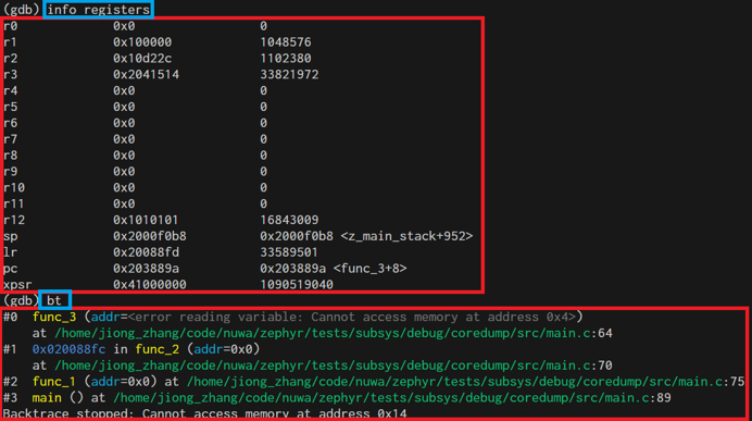
Example of viewing results with gdb commands:
Coredump Pseudo Device
The coredump device is a pseudo device driver that provides configuration and function interfaces, allowing users to customize memory regions to be saved during coredump.
Enable the Coredump pseudo device by turning on macro CONFIG_COREDUMP_DEVICE. There are two types of Coredump pseudo devices:
COREDUMP_TYPE_MEMCPY: During coredump, dump memory entries defined in device tree and memory entries registered at runtime.COREDUMP_TYPE_CALLBACK: During coredump, execute registered callback functions and save an array regioncoredump_bytes[].
The two types are defined in code as follows:
enum COREDUMP_TYPE {
    COREDUMP_TYPE_MEMCPY = 0,
    COREDUMP_TYPE_CALLBACK = 1,
};
Device required configuration information:
struct coredump_config {
    /* Type of coredump device */
    enum COREDUMP_TYPE type;
    /* Length of memory_regions array */
    int length;
    /* Memory regions specified in device tree */
    size_t memory_regions[];
};
Device required configuration information corresponding to DTS configuration:
/ {
    coredump_device0: coredump-device0 {
        compatible = "zephyr,coredump";
        coredump-type = "COREDUMP_TYPE_MEMCPY";
        status = "okay";
    };
    coredump_devicecb: coredump-device-cb {
        compatible = "zephyr,coredump";
        coredump-type = "COREDUMP_TYPE_CALLBACK";
        status = "okay";
        memory-regions = <0x0 0x4>;
    };
};
Note
COREDUMP_TYPE_MEMCPYtype device does not requirememory-regionsproperty in dts; memory regions to be saved for this type can be added using API in code;COREDUMP_TYPE_CALLBACKtype device must havememory-regionsproperty, where the first value0x0is the memory start address but does not take effect; during actual use, the memory start address is obtained from&coredump_bytes[0]; the second value0x4is the size of memory to save, which will createcoredump_bytes[]based on this value. The actual memory region saved during coredump is this coredump_bytes[].
Information needed during runtime:
struct coredump_data {
    /* Memory regions registered at run time */
    sys_slist_t region_list;
    /* Callback to be invoked at time of dump */
    coredump_dump_callback_t dump_callback;
};
Information needed during runtime can be registered using the following device APIs:
static DEVICE_API(coredump, coredump_api) = {
    .dump = coredump_impl_dump,                           // Called during a coredump to dump memory from the coredump pseudo device
    .register_memory = coredump_impl_register_memory,     // Register a memory region for a COREDUMP_TYPE_MEMCPY device
    .unregister_memory = coredump_impl_unregister_memory, // Unregister a memory region for a COREDUMP_TYPE_MEMCPY device
    .register_callback = coredump_impl_register_callback, // Register a callback function for a COREDUMP_TYPE_CALLBACK device
};
In the coredump() main flow, process_memory_region_list() is called to handle memory region dumps. Pseudo device dumps are also called in this function. The relevant implementation is as follows:
void process_memory_region_list(void)
{
...
#if defined(CONFIG_COREDUMP_DEVICE)
#define MY_FN(inst) process_coredump_dev_memory(DEVICE_DT_INST_GET(inst));
     DT_INST_FOREACH_STATUS_OKAY(MY_FN)
#endif
}

#if defined(CONFIG_COREDUMP_DEVICE)
static void process_coredump_dev_memory(const struct device *dev)
{
     DEVICE_API_GET(coredump, dev)->dump(dev);
}
#endif
Note
Even if the DEBUG_COREDUMP_MEMORY_DUMP_MIN configuration is selected, additional memory information can be included in the dump file through one or more coredump devices.
Online Debugging
Online debugging refers to real-time control and observation of program execution through debugging interfaces in the target environment where the code actually runs, including setting breakpoints, single-stepping, viewing/modifying memory and registers, monitoring thread and peripheral status, etc.
Zephyr’s meta-tool west provides some debug-related commands that support connecting a debugger to a development board from a Zephyr build directory and opening a debug console (e.g., GDB session).
west debug Usage
You can use west debug -h to view help information, which includes explanations for each parameter.
zephyr/scripts/west_commands/debug.py implements three subclasses for debug functionality:
debug: Connect to the development board via debug protocol, program the flash, then direct the user to the debugger interface with symbol table loaded from the current binary, and block until the debugger exits. (Equivalent to starting gdbserver+gdb)debugserver: Connect via board-specific debug protocol, then reset and halt the target. Ensures the user can now connect to the debug server with symbol table loaded from the binary. (Equivalent to starting gdbserver)attach: Connect to the development board via debug protocol, then direct the user to the debugger interface with symbol table loaded from the current binary, and block until exit. Unlike ‘debug’ command, this command does not program the flash. (Equivalent to starting gdb)
west debug command usage examples:
west debug            // If the default debug runner is J-Link, this starts JLinkGDBServer and the GDB debugger.
west debug -i ip:port // Start JLinkGDBServer and connect it to a remote JLinkRemoteServer at ip:port.
When using GDB for online debugging, the development board must be connected to the host computer via a J-Link probe. The following diagram shows three typical scenarios based on different connection methods and tools used. For detailed debugging methods and commands, see Online Debugging
Code on Windows computer, development board connected to Windows computer via jlink, debug using west debug.

Code on Linux server, development board connected to Windows computer via jlink, debug using gdb command line tool.

Code on Linux server, development board connected to Windows computer via jlink, debug using west debug command line.

Note
The west debug command starts JLinkGDBServer and arm-none-eabi-gdb, so using the west debug command requires both to be present on the host.
MCUboot Introduction
MCUboot Introduction
MCUboot is a secure bootloader for 32-bit microcontrollers. It defines a common infrastructure for bootloaders and system flash layouts on microcontroller systems, and provides a secure bootloader that enables easy software upgrades. MCUboot is not dependent on any specific operating system or hardware, but relies on the hardware porting layer of the operating system it works with. MCUboot can be easily used in Zephyr, and it also supports Using RSIP Encryption.
Boot Process
The system boot process is completed by two-stage boot: ROM boots the Bootloader, and Bootloader boots the app. When MCUboot serves as the bootloader, the boot flow is shown in the following figure:

The figure above focuses on describing the main process from the Zephyr/MCUboot project perspective. For detailed functional information, please refer to Free RTOS Boot Process
Flash Layout
MCUBoot’s Flash Layout design requirements are mainly based on OTA support and security/stability considerations. In Swap_using_move and Swap_using_offset OTA modes, each APP firmware requires two slots. For details, see Flash Partition Mapping
To modify the Flash Layout, simply modify the macro definitions at the header of the corresponding dts file, and other variables will be automatically calculated. The main values to modify are:
FLASH_BASE_PHY: flash physical base addressROM_JUMP_ADDR: the address where ROM jumps to bootloader, this address determines the flash logical base addressIMG0_LOGIC_ADDR/IMG1_LOGIC_ADDR: logical address of app firmwareBOOT_SLOT_BASE/BOOT_SLOT_SIZE: bootloader offset (based on flash base address) and sizeIMG0_SLOT_SIZE/IMG1_SLOT_SIZE: size of app firmware. App and bootloader slots are tightly arranged, so the range of each slot can be calculated based on offset and size
File path: zephyr/boards/realtek/rtl8721f_evb/rtl8721f_evb_mcuboot.dts
/**
* BOOT refers to mcuboot bootloader, at smallest physical address
* IMG0 refers to km4tz, is primary image, at bigger physical address
* IMG1 refers to km4ns, is secondary image, at smaller physical address
*/

/* Parameters below are set based on the hardware/rom/custom by user */
#define FLASH_BASE_PHY 0x08000000
#define ROM_JUMP_ADDR 0x10400020

/*WARNING: BETTER keep consistent with ameba_layout.ld::KM4TZ_IMG2_XIP exclude header 0x20*/
#define IMG0_LOGIC_ADDR 0x04000000
/*WARNING: MUST keep consistent with ameba_layout.ld::KM4NS_IMG2_XIP exclude header 0x20*/
#define IMG1_LOGIC_ADDR 0x02000000

#define BOOT_SLOT_BASE 0x0
#define BOOT_SLOT_SIZE DT_SIZE_K(80)  /* 0x14000 */

#define IMG0_SLOT_SIZE DT_SIZE_K(512) /* 0x80000 */
#define IMG1_SLOT_SIZE DT_SIZE_K(512) /* 0x80000 */
Note
After modifying slot-related parameters, you should also update the values after each partition@ in spic/flash0/partitions to match their reg[0] values to avoid compilation warnings.
MCUboot Bootloader Firmware
The MCUboot bootloader firmware format and code execution address must meet the requirements of its upper-level bootloader ROM, so it is similar to the ameba bootloader. Currently, the entire bootloader executes in XIP mode.
Firmware Format
After code compilation is complete, the resulting zephyr.bin needs further processing to generate firmware that meets ROM requirements. The relationship and structure of each part is shown in the following figure:

It is composed of three parts concatenated together:
manifest.binboot_xip.bin: obtained by adding a 32-byte header tozephyr.binboot_ram.bin: obtained by adding a 32-byte header to an empty body, its purpose is to satisfy ROM verification requirements
MCUboot App Firmware
The MCUboot app firmware format must follow MCUBoot requirements. For details, please refer to Firmware Format
Twister Introduction
twister Introduction
twister is zephyr’s built-in testing framework, used for automated large-scale compilation and execution of test cases in zephyr, to ensure the correctness and stability of zephyr across different hardware platforms and configurations.
twister identifies test suites by scanning specific YAML configuration files (such as testcase.yaml) in the source code repository, and compiles and executes them. The final status of tests is recorded in twister.json and other report files.
Zephyr official provides detailed twister documentation.
twister Windows Environment Setup
When running twister on Windows, you need to set up the runtime environment, including installing the toolchain, Python environment, and configuring environment variables.
Refer to Select and Update the Operating System to install the environment. After installation, you can see the toolchain and Python environment directories in the rtk_toolchain directory.
C:\rtk-toolchain
|-- asdk-12.3.1-4431        # Toolchain
|-- prebuilts-win-1.0.3     # Tool package containing Python environment
Configure the following user environment variables:
Variable Name |
Variable Value |
|---|---|
GNUARMEMB_TOOLCHAIN_PATH |
C:\rtk-toolchain\asdk-12.3.1-4431\mingw32\newlib |
ZEPHYR_TOOLCHAIN_VARIANT |
gnuarmemb |
When using the system environment, add the following paths to the Path variable:
C:\rtk-toolchain\prebuilts-win-1.0.3\bin
C:\rtk-toolchain\prebuilts-win-1.0.3\cmake\bin
C:\rtk-toolchain\prebuilts-win-1.0.3\python3
C:\rtk-toolchain\prebuilts-win-1.0.3\python3\Scripts
Install Python packages that twister depends on:
python -m pip install -r .\zephyr\scripts\requirements.txt
python -m pip install -r .\tools\requirements.txt
Note
When the Python environment is set up correctly, in Powershell, you can use python .\scripts\twister –help to see the twister help message successfully.
twister Usage
twister tool supports setting parameters via command line, common parameters are as follows:
-p PLATFORM, --platform PLATFORM: Specify the test platform, can be used multiple times.-T TESTSUITE_ROOT, --testsuite-root TESTSUITE_ROOT: Root directory to recursively search for test suites, can be used multiple times. Default values are samples/ and tests/ directories under the zephyr root directory.-s TEST, --test TEST, --scenario TEST: Run only the specified test suite scenario, can be used multiple times.-t TAG, --tag TAG: Specify tags to limit which tests to run. Multiple calls will be treated as logical “or” relationship. No tag filtering by default.--test-config TEST_CONFIG: Specify the file path containing the test plan and configuration.--device-testing: Run tests on device.--device-serial DEVICE_SERIAL: Serial port device used to access the development board (e.g., COM12, /dev/ttyACM0).--device-serial-baud DEVICE_SERIAL_BAUD: Set serial port device baud rate (default: 115200).--west-flash [WEST_FLASH]: Configure west flash parameters.--flash_before: Flash first, then connect to serial port.--short_build_path: Create shorter build directory paths. Recommended to enable this option on Windows.--retry-build-error: Retry build errors.--retry-failed RETRY_FAILED: Retry failed tests, up to the specified number of times.
twister Usage Examples
Specify the test directory via -T, which will execute all test suites in that directory:
nuwa\zephyr> python .\scripts\twister --short-build-path --device-testing `
  --flash-before --west-flash="--port=COM12" --device-serial COM12 --device-serial-baud 1500000 `
  --platform rtl8721f_evb `
  -T tests/kernel/threads/dynamic_thread_stack/
The above command will run 8 test suites in tests/kernel/threads/dynamic_thread_stack/tescase.yaml.
You can further specify a single test suite via –test:
nuwa\zephyr> python .\scripts\twister --short-build-path --device-testing `
  --flash-before --west-flash="--port=COM12" --device-serial COM12 --device-serial-baud 1500000 `
  --platform rtl8721f_evb `
  -T tests/kernel/threads/dynamic_thread_stack/ `
  --test kernel.threads.dynamic_thread.stack.no_pool.no_alloc.no_user
zephyr provides two levels of batch tests, smoke and acceptance, in zephyr/tests/test_config.yaml.
The smoke test set is smaller and is usually used as the first step of continuous integration. If the smoke test fails, it usually means there is a serious defect, and you can immediately abort subsequent more time-consuming tests.
The acceptance test set includes smoke and is more comprehensive but more time-consuming than smoke.
zephyr smoke batch test command:
nuwa\zephyr> python .\scripts\twister --short-build-path --device-testing `
  --flash-before --west-flash="--port=COM12" --device-serial COM12 --device-serial-baud 1500000 `
  --platform rtl8721f_evb `
  -T tests --test-config=".\tests\test_config.yaml" --level="smoke" `
  --retry-failed 3 --retry-build-errors
zephyr acceptance batch test command:
nuwa\zephyr> python .\scripts\twister --short-build-path --device-testing `
  --flash-before --west-flash="--port=COM12" --device-serial COM12 --device-serial-baud 1500000 `
  --platform rtl8721f_evb `
  -T tests --test-config=".\tests\test_config.yaml" --level="acceptance" `
  --retry-failed 3 --retry-build-errors
Note
Replace the serial port specified by –west-flash and –device-serial, and the platform specified by –platform in the above commands according to your actual situation.
Custom Batch Test Suite
If you want to execute a batch of specified test suites via twister, you can refer to the format of zephyr/tests/test_config.yaml to customize a test configuration file, and then specify the file and level via --test-config and --level= parameters like the smoke and acceptance batch tests above.
In the test configuration file, you can define test levels (name under levels), level dependencies (inherits), and use regular expressions in adds to specify test suites.
The following example defines two test levels, smoke and acceptance, where acceptance inherits from smoke.
platforms:
  override_default_platforms: false
  increased_platform_scope: true
levels:
  - name: smoke
    description: >
      A plan to be used verifying basic zephyr features on hardware.
    adds:
      - kernel.threads.*
      - kernel.timer.behavior
      - arch.interrupt
      - boards.*
      - drivers.gpio.1pin
      - drivers.console.uart
      - drivers.entropy
  - name: acceptance
    description: >
      More coverage
    inherits:
      - smoke
    adds:
      - kernel.*
twister Configuration Files
Board Configuration File
The twister board configuration file describes the hardware characteristics and configuration information of the development board, using YAML format, located in each board directory, usually named <board>.yaml. For example, the twister board configuration file for rtl8721f_evb is zephyr/boards/realtek/rtl8721f_evb/rtl8721f_evb.yaml.
For the meaning of each field in the twister board configuration file, refer to the official documentation Board Configuration .
testcase.yaml
testcase.yaml is the definition file for tests in the tests directory, read by twister to declare test scenarios, configurations, and execution rules for test code in the current directory.
It has the following purposes:
Control test scope and behavior through filter, platform_allow, platform_exclude and other configurations, precisely specifying under what conditions, on which boards, and with what configuration a test runs.
Use fields like min_ram to avoid flashing large memory tests to resource-constrained development boards.
Use tags to classify tests, allowing quick execution of a certain category of tests.
Define how to determine test pass/fail from console output through harness and harness_config, enabling automated verification.
For the meaning of each configuration item in the testcase.yaml file, refer to the official documentation Test Scenario Identifier .
Among them:
tags: <list of tags> (required), a set of string tags for the test scenario. You can filter test suites to run via twister command line
--tagand--exclude_tag.depends_on: <list of features>, dependent features need to be supported in the
supportedfeature list in Board Configuration File, otherwise the test suite will be filtered out.platform_exclude: <list of platforms>, if you don’t want to execute a certain test suite, you can exclude it via platform_exclude. For example:
platform_exclude:
    - rtl8721f_evb
    - rtl872xda_evb
sample.yaml
sample.yaml is used to describe a demo program located in the samples/ directory to twister. The meaning of each configuration item in this file can be referred to testcase.yaml.
twister Reports
When executing twister, a twister-out directory is generated in the current directory by default to store binary files, logs, reports, etc.
testplan.json: Test plan, can be used to understand which test suites will be executed.twister.json: Execution results of test suites.twister.log: Execution process log of the twister tool itself. Records compilation, flashing, execution steps and errors. Can be used to diagnose twister execution or environment issues.twister.xml,twister_report.xml,twister_suite_report.xml: Other forms of reports.
Below is an example of a successful test suite result in twister.json:
{
    "name":"tests/drivers/console/hello_world/drivers.console.uart",
    "arch":"arm",
    "platform":"rtl8721f_evb/rtl8721f",
    "path":"tests\\drivers\\console\\hello_world",
    "run_id":"852209a4da4005a76fee86f9a772c087",
    "runnable":true,
    "retries":0,
    "toolchain":"gnuarmemb",
    "status":"passed",
    "execution_time":"8.44",
    "build_time":"493.38",
    "testcases":[
        {
            "identifier":"drivers.console.uart",
            "execution_time":"8.44",
            "status":"passed"
        }
    ]
}
Below is an example of a failed test suite result in twister.json, which records the reason for failure:
{
    "name":"tests/kernel/mem_protect/syscalls/kernel.memory_protection.syscalls.timeslicing",
    "arch":"arm",
    "platform":"rtl8721f_evb/rtl8721f",
    "path":"tests\\kernel\\mem_protect\\syscalls",
    "run_id":"6ce8788b17745a48c339e75dfdf479b3",
    "runnable":true,
    "retries":0,
    "toolchain":"gnuarmemb",
    "status":"failed",
    "log":"",
    "reason":"Timeout",
    "execution_time":"198.54",
    "build_time":"651.04",
    ......
}
For the meaning of test suite and test case statuses, see the official documentation twister status.
twister Test Failure Diagnosis
If a test suite fails, you can try the following methods to diagnose the problem:
Search for the test suite name in the
twister.jsonreport to confirm its execution status and failure reason, and get preliminary error information.Go to the test suite’s output directory in twister-out and check the following log files:
build.log: Diagnose compilation errorsdevice.logandhandler.log: Diagnose runtime issues, such as flashing errors, timeouts.
Use the twister –test <test suite name> ….. command to re-run the test individually. This helps determine if the failure is a problem with the test suite itself, or caused by test execution order, environment residue, or other factors.
If a large number of test suites show Timeout errors during batch testing, a common reason is that a certain test suite failed to correctly respond to the device flashing command reboot uartburn after running, causing subsequent tests to fail to execute normally.
You can follow these steps to identify which specific test suite caused the problem:
Connect the tracetool log tool, then restart the development board.
From the boot log above, find the value of the test suite’s
RunID, for example:...... Unexpected fault during test =================================================================== RunID: 6ce8788b17745a48c339e75dfdf479b3 PROJECT EXECUTION FAILEDIn the
twister.jsonreport, search for the test record that matches the above RunID value. The test suite corresponding to that record may be the root cause of the subsequent series of timeout issues.
CANbus Subsystem Introduction
Sample Project Introduction
Zephyr implements an ISO-TP protocol CAN bus subsystem sample project in the zephyr/samples/subsys/canbus/isotp directory.
This sample demonstrates how to use the ISO-TP library to exchange messages between two development boards:
A long message, sent using a block size (BS) of 8 frames.
A short message, with a minimum separation time (STmin) of 5 milliseconds.
The short message send function call is non-blocking; the long message send function call is blocking.
Note
The default configuration of the rtl8721f_evb development board has loopback mode enabled, so no additional wiring is required. A single development board can run the sample project normally.
Build Command
Use the following command to build the isotp sample project:
west build -b rtl8721f_evb zephyr/samples/subsys/canbus/isotp
The default configuration can be built and run normally. For modifying configuration details, see isotp Sample Project Configuration.
Sample Output
Start sending data
[00:00:00.000,000] <inf> can_driver: Init of CAN_1 done
========================================
|   ____  ___  ____       ____  ____   |
|  |_  _|/ __||    | ___ |_  _||  _ \  |
|   _||_ \__ \| || | ___   ||  | ___/  |
|  |____||___/|____|       ||  |_|     |
========================================
Got 248 bytes in total
This is the sample test for the short payload
TX complete cb [0]
Note
The values in the above output may vary.
ISO-TP Protocol Introduction
ISO-TP (ISO 15765-2) is a “segmentation and reassembly” upper-layer protocol built on classic frames. It does not change the physical/link layer structure of classic frames, but instead places its own “protocol header/type field + data” into the Data Field of classic frames, and defines its own frame types (SF/FF/CF/FC) and protocol content within. It can be further divided into the following four frame types:
Single Frame (SF)
First Frame (FF)
Consecutive Frame (CF)
Flow Control Frame (FC)
Single Frame (SF)
If the data payload is 7 bytes or less, a single frame is used for data transmission in the ISO-TP protocol. The first byte of the data field is used for PCI (Protocol Control Information). This byte is further divided into two parts: the upper 4 bits of the first byte indicate the frame type, and the lower 4 bits indicate the DL (data length).

Key values and encoding description:
DL (Data Length): Data length of this frame (1..7)
First Frame (FF)
The first frame is the initial message of a multi-frame message packet in the ISO-TP protocol. It is used when segmented data exceeding 7 bytes must be transmitted. The first frame contains the length of the complete data packet as well as the initial data. In FF, the first 2 bytes are used for PCI, where the upper 4 bits of the first byte are used for frame type, and the lower 4 bits together with the next 1 byte (total 8+4 = 12 bits) of the data field are used for DL (2^12 = 4095 data bytes). Therefore, in FF, only 6 bytes of data can be transmitted initially. This frame is responsible for sending information to the receiver about how many total data bytes will be sent.

Key values and encoding description:
DL (Data Length): Total length of complete data (12 bits), including all subsequent CF data
Consecutive Frame (CF)
The main task of the transport protocol or ISO-TP protocol is to transmit such messages (which cannot be transmitted as a single protocol data unit (PDU) due to length) that are segmented into multiple separate PDU messages.

Key values and encoding description:
Sequence Number SN (lower 4 bits of CF): Values 0..15, sender increments SN = (SN+1) mod 16 after each CF; per specification, the first CF after FF has SN=1
Flow Control Frame (FC)
The flow control mechanism of the ISO-TP protocol is used to configure the sender to match the receiver’s attributes (timing, available receive buffers, receive readiness). Flow Control (FC) is always sent by the receiver to determine how the sender transmits data based on the receiver’s attributes.

Key values and encoding description:
FlowStatus (FS, lower 4 bits of FC)
0 = CTS (Clear To Send): Continue sending, with BS and STmin parameters
1 = WAIT: Please wait, sender increments WFT count, abort if exceeds WFTmax
2 = OVFLW: Receiver buffer insufficient, immediately abort this transmission
Block Size (BS)
0: No block flow control (continuous CF from FF until completion, no intermediate FC needed)
1..255: After sending BS number of CFs, sender must wait for new FC
STmin (FC byte 2)
0x00..0x7F: Unit is milliseconds (ms)
0xF1..0xF9: Unit is 100 microseconds (100 µs steps)
Other values reserved; if the implementation does not support microsecond encoding, typically treated as 0 (refer to specific stack implementation)
Typical Examples
(Classic frames, standard addressing, hexadecimal)
SF (3-byte PDU, data AA BB CC)
03 AA BB CC 00 00 00 00FF (total length 0x0014=20, first frame data 12 34 56 78 9A BC)
10 14 12 34 56 78 9A BCCF (SN=1, data DE AD BE EF 01 02 03)
21 DE AD BE EF 01 02 03FC (CTS, BS=8, STmin=5ms)
30 08 05 00 00 00 00 00
CAN Bus Subsystem Introduction
The directories and files related to the CAN bus subsystem in Zephyr are shown below:
nuwa $
   ├── modules
   │   ├── hal/realtek/ameba/amebaG2/source/fwlib # hal
   │   └── lib/canopennode/                           # canopennode third-party library
   └── zephyr
       ├── include/zephyr/drivers/can.h               #macros, structs, _syscall api (calls driver)
       ├── drivers
       │   ├── can
       │   │   ├── can_ameba.c                        #driver_api
       │   │   ├── can_common.c                       #common api
       │   │   └── can_shell.c                        #shell command implementation
       │   └── net/canbus.c                           #canbus_api (calls _syscall api)
       ├── dts
       │   ├── arm/realtek/amebaG2/amebaG2.dtsi       #driver node
       │   └── bindings/can/realtek,ameba-can.yaml    #yaml
       ├── modules
       │   └── canopennode/                           #canopen protocol implementation and wrapper (calls _syscall api)
       ├── subsys
       │   ├── canbus/isotp/                          #implements ISO-TP session layer, including segmentation, flow control, etc. (calls _syscall api)
       │   └── net
       │         ├── ip/canbus_socket.c              #mapping and calling from "socket" to "L2 send entry" (bridges upper and lower layers)
       │         ├── l2/canbus/canbus_raw.c          #L2 link layer (calls canbus_api)
       │         └── lib/socket_can.c                #AF_can socket layer (calls IP layer interface)
       ├── samples
       │   ├── drivers/can/
       │   ├── modules/canopennode/                   #canopennode sample project
       │   └── subsys
       │       ├── canbus/isotp/                      #isotp send sample project
       │       └── net/socket/can/                    #socket sample project
       └── tests
           ├── drivers/can/
           └── subsys/canbus/
isotp Sample Project Configuration
Configuration can be divided into two types of files:
DTS: Includes
*.dts,*.dtsi,*.yaml,*.overlayfile types, used to define DTS variables and attribute rules.Kconfig:
*.conffile types are used to define default values for configuration items.
Users can modify the system’s default configuration by editing the rtl8721f_evb.overlay and rtl8721f_evb.conf files in the zephyr/samples/subsys/canbus/isotp/boards directory.
DTS Configuration
Device nodes are defined in zephyr/dts/arm/realtek/amebaG2/amebaG2.dtsi:
/ {
    soc {
        can0: can@41005000 {
            compatible = "realtek,ameba-can";
            reg = <0x41005000 0x400>;
            clocks = <&rcc AMEBA_CAN0_CLK>;
            interrupts = <60 0>;
            status = "disabled";
        };
  }
}
Pins used by the device are defined in zephyr/boards/realtek/rtl8721f_evb/rtl8721f_evb-pinctrl.dtsi:
&pinctrl {
    compatible = "realtek,ameba-pinctrl";
    can0_default: can0_default {
        group1 {
            pinmux = <AMEBA_PINMUX('A', 25, AMEBA_CAN0_TX)>,
                     <AMEBA_PINMUX('A', 26, AMEBA_CAN0_RX)>;
            bias-pull-up;
        };
    };
}
The device used by Zephyr’s isotp sample project is specified by the zephyr,canbus property in the chosen node, so you need to select a device in zephyr/samples/subsys/canbus/isotp/boards/rtl8721f_evb.overlay:
/ {
    chosen {
        zephyr,canbus = &can0;
    };
};

&can0 {
    pinctrl-0 = <&can0_default>;
    pinctrl-names = "default";
    status = "okay";
};
Kconfig Configuration
Basic configurations are set in zephyr/samples/subsys/canbus/isotp/prj.conf. Refer to the configuration item descriptions below for the meaning of each configuration:
CONFIG_LOG=y
CONFIG_CAN=y
CONFIG_CAN_MAX_FILTER=8
CONFIG_ISOTP=y
CONFIG_ISOTP_RX_SF_FF_BUF_COUNT=2
When building the image for the rtl8721f_evb development board, you can enable loopback mode in zephyr/samples/subsys/canbus/isotp/boards/rtl8721f_evb.conf. After enabling loopback mode, no additional wiring is required, and a single development board can run the sample project normally:
CONFIG_SAMPLE_LOOPBACK_MODE=y
The isotp Kconfig configuration items are located in zephyr/subsys/canbus/isotp/Kconfig. Below are descriptions of some configurations:
- ISOTP_WFTMAX:
WFTmax, the maximum number of WAIT occurrences the sender can accept when the receiver returns FC=WAIT; transmission is aborted if exceeded.
- ISOTP_BS_TIMEOUT:
Timeout for the sender while waiting for the next flow control frame (FC). The timer is started after sending an FF or after sending a complete block of CFs.
- ISOTP_A_TIMEOUT:
As/Ar send/receive timeout (internal protocol stack protection timer for send operations and receive responses).
- ISOTP_CR_TIMEOUT:
Timeout for the receiver while waiting for the next consecutive frame (CF).
- ISOTP_REQUIRE_RX_PADDING:
Requires received SF, FC, and the last CF to be padded to full DLC; unused bytes must be padded.
- ISOTP_ENABLE_TX_PADDING:
Sender pads frames as needed, using 0xCC as the padding value (Bosch recommendation).
- ISOTP_RX_BUF_COUNT:
Number of receive data buffer blocks (blocks in net_buf pool), used to hold data during reassembly.
- ISOTP_RX_BUF_SIZE:
Size of each receive data block (bytes).
- ISOTP_RX_SF_FF_BUF_COUNT:
Number of pre-allocated buffers dedicated to receiving single frames (SF) and first frames (FF).
- ISOTP_USE_TX_BUF:
When sending, the application data is copied to an internal net_buf; the caller can immediately release the original data.
- ISOTP_TX_BUF_COUNT:
Number of send data buffer blocks (for ISOTP_USE_TX_BUF mode).
- ISOTP_BUF_TX_DATA_POOL_SIZE:
Total size of the memory pool where send buffers are allocated (bytes).
- ISOTP_ENABLE_CONTEXT_BUFFERS:
Enables “context buffers” (memory slab) to store send context, making “send-and-forget” possible.
- ISOTP_TX_CONTEXT_BUF_COUNT:
Maximum number of concurrent/queued send contexts.
- ISOTP_CUSTOM_FIXED_ADDR:
Enables custom “Fixed Addressing” ID encoding.
When the ISOTP_CUSTOM_FIXED_ADDR configuration is enabled, the following configurations also need to be set:
- ISOTP_FIXED_ADDR_SA_POS:
Bit start position of source address (SA) in the identifier.
- ISOTP_FIXED_ADDR_SA_MASK:
Mask for extracting source address.
- ISOTP_FIXED_ADDR_TA_POS:
Bit start position of target address (TA).
- ISOTP_FIXED_ADDR_TA_MASK:
Mask for extracting target address.
- ISOTP_FIXED_ADDR_PRIO_POS:
Bit start position of priority field.
- ISOTP_FIXED_ADDR_PRIO_MASK:
Mask for extracting priority field.
- ISOTP_FIXED_ADDR_RX_MASK:
Mask for receive filtering, typically set to loose filtering that matches any priority and source address.