Zephyr TF-M User Guide
TF-M Overview
Trusted Firmware-M (TF-M) is the reference implementation of the Platform Security Architecture (PSA) IoT security framework. It defines and implements an architecture and a set of software components that aim to address some of the major security concerns in IoT products.
The following table describes the structure under the root folder and some of the possible folders.
Folder name |
Description |
|---|---|
bl1 |
First stage immutable bootloader |
bl2 |
Second stage bootloader based on MCUBoot |
cmake |
CMake files of the build system |
config |
Configuration files |
docs |
Documentation |
interface |
RoT service APIs for client calls |
lib |
Third-party libraries |
platform |
Platform files |
secure_fw |
Secure firmware |
tools |
Tools used for building in scripts |
Architecture Overview
The following figure gives an overview of the functionality and principles of Trusted Firmware-M (TF-M):
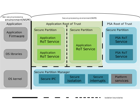
The following sections briefly describe the different concepts mentioned in the figure.
SPE and NSPE
The key concept of TF-M is to achieve security by separating the Secure Processing Environment (SPE, the trusted world) from the Non-Secure Processing Environment (NSPE, the non-trusted world).
SPE (Secure Processing Environment): Runs in the Secure World of Cortex-M TrustZone.
The SPE is the core runtime domain of TF-M. It manages critical security assets such as keys, the crypto engine, and trusted storage, and provides security services to the NSPE through PSA APIs. The code and data in the SPE are protected by hardware isolation and cannot be directly accessed by the NSPE, ensuring the physical isolation of the security boundary.
NSPE (Non-Secure Processing Environment): Runs in the Non-Secure World of TrustZone.
The NSPE is the runtime domain for applications and the RTOS (such as Zephyr or FreeRTOS), and is responsible for handling regular business logic, peripheral drivers, network communication, and so on. The NSPE calls the security services provided by the SPE through PSA APIs. It cannot directly operate on secure resources, and all sensitive operations must be delegated to the SPE.
PRoT and ARoT
PRoT (Platform Root of Trust) is the most core trust foundation in the PSA security architecture.
The PRoT contains the SPM (Secure Partition Manager) of TF-M and the platform initialization code. It is responsible for the secure configuration during system startup (SAU/MPC/PPC), firmware verification, and secure partition management. The PRoT has the highest privilege and runs at the lowest isolation level. It is the “trust anchor” of the entire system security; once it is compromised, it will lead to a global security failure.
ARoT (Application Root of Trust) is a collection of security service partitions running in the Secure World.
The ARoT contains the concrete security service implementations such as PSA Crypto, Trusted Storage, and Attestation, providing standardized security function interfaces for the NSPE. The ARoT is managed and isolated by the PRoT, and different isolation levels can be configured between service partitions. The ARoT can be updated and upgraded without affecting the PRoT.
Isolation level
Isolation level 1: The secure/non-secure separation described in the Secure and Non-Secure Processing Environment section.
Isolation level 2: ARoT services cannot access other parts of the SPE.
Isolation level 3: ARoT services cannot access other parts of the SPE or other ARoT services.
SPM
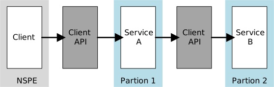
FF-M (Firmware-Framework-M) is an architecture specification defined by Arm. It defines how secure firmware should be organized and isolated, as well as the model and invocation mechanism. The service access flow defined in it is as follows:
Note
FF-M refers to the cumulative result of two specifications: FF-M v1.1 update and FF-M v1.0.
SPM (Secure Partition Manager) is the core of an FF-M-compliant implementation. It establishes and maintains a firmware framework that manages the partition runtime in accordance with FF-M, and implements the Client API and the Secure Partition API.
Each service exposes its service ID (SID) and handle for client access. A client accesses a service through the SID or handle via the Client API. A partition uses the Secure Partition API when it needs to operate on client data or respond to client requests.
Partition Runtime Model
A partition must run in one of the following runtime models: the Inter-Process Communication (IPC) model or the Secure Function (SFN) model.
An implementation that contains only Secure Function (SFN) partitions is more suitable for resource-constrained devices; such an implementation is called an SFN model implementation. When there is an Inter-Process Communication (IPC) partition in the system, it is called an IPC model implementation.
IPC Model
A partition running under the Inter-Process Communication (IPC) model looks like a classic process. There is only one thread inside the partition, and it continuously waits for signals. The Secure Partition Manager (SPM) converts the information obtained from the client API calls into messages and signals the partition. The partition calls the corresponding service function indicated by the signal and its bound message, and replies the result returned by the service to the client. The advantages of this model:
It provides better isolation by restricting the data interaction interface. Data is best processed in a local buffer.
It provides a mechanism to handle multi-service access. There is no memory mapping mechanism in an MCU system, so if service access adopts a function-call-based mechanism, it is difficult to provide multiple function-call contexts when serving multi-threaded clients. This model converts multiple service accesses into messages, and the partition handles the service accesses in the messages one by one.
SFN Model
A Secure Function (SFN) model partition is similar to a library. Each service exists inside the partition in the form of a function entry. The SPM starts the target service function after finding the service. The whole process (from the client to the service function) is a single function call. This model saves the workload used for inter-process communication scheduling.
At the same time, it relaxes the data interaction mechanism, for example allowing direct memory access (MMIOVEC). However, due to the difficulty of maintaining multiple call contexts, it is difficult to implement multi-threaded client service access.
PSA Certified APIs
PSA (Platform Security Architecture) is a full-stack security architecture standard system for IoT devices introduced by ARM. Its goal is to unify the MCU security architecture and API specifications, and to solve the fragmentation of IoT security.
The core content of the PSA system includes three dimensions:
Security architecture specification: Defines a hardware-isolation-based IoT security architecture model, clarifying the design requirements for core capabilities such as secure boot, isolation, and attestation.
Standardized API interfaces: Defines a unified PSA Functional API specification, covering the interface standards of core security services such as cryptography, trusted storage, and device attestation.
Security evaluation and certification system: Defines a graded PSA Certified certification system, providing a standardized evaluation and certification basis for the security capabilities of IoT devices.
The PSA Certified APIs are exposed to the non-secure side through Non-Secure Callable (NSC) interfaces. The NSC callable interface is a security mechanism that enables controlled communication between the NSPE and the SPE. Using this mechanism, applications running in the NSPE can securely communicate with the RoT services in the SPE.
TF-M Services
A security service (Service for short) is a component in the SPE that provides security functions, while a client is a user of a Service. When a Service accesses a service it depends on, it acts in the role of a client. Services are grouped into secure partitions (also called partitions). A partition:
Contains services with the same purpose.
Provides the isolation boundary required by the implementation.
Is a unit of software development.
Each service exposes its service ID (SID) and handle for client access. A client accesses a service through the SID or handle via the Client API. A partition uses the Secure Partition API when it needs to operate on client data or respond to client requests.
Protected Storage Service
The TF-M Protected Storage (PS) service is an ARoT service that implements the PSA Protected Storage API. This service usually relies on the hardware isolation of the flash access domain. The current version also relies on hardware to isolate the flash region from non-secure access. Even without hardware isolation, the confidentiality and integrity of the data can still be guaranteed.
The PS service adopts an AES-GCM-based AEAD (Authenticated Encryption with Associated Data) encryption strategy as a reference to protect the integrity and authenticity of data. PS reuses the non-hierarchical file system provided by the TF-M Internal Trusted Storage service to store encrypted and authenticated objects.
The PS service exposes the following mandatory PSA PS interfaces, version 1.0:
psa_status_t psa_ps_set(psa_storage_uid_t uid, size_t data_length, const void *p_data, psa_storage_create_flags_t create_flags);
psa_status_t psa_ps_get(psa_storage_uid_t uid, size_t data_offset, size_t data_size, void *p_data, size_t *p_data_length);
psa_status_t psa_ps_get_info(psa_storage_uid_t uid, struct psa_storage_info_t *p_info);
psa_status_t psa_ps_remove(psa_storage_uid_t uid);
uint32_t psa_ps_get_support(void);
These PSA PS interfaces and PS TF-M types are defined and documented in interface/include/psa/protected_storage.h, interface/include/psa/storage_common.h,
and interface/include/tfm_ps_defs.h, where you can find detailed comments on the interface functions and their usage.
You can find usage examples in the psa_protected_storage sample project in the Zephyr Sample Projects section below. The test source code of the tfm_psa_test and tfm_regression_test sample projects is in the test code repository, and you can also check the usage in the test code repository.
Internal Trusted Storage Service
PSA Internal Trusted Storage (ITS) is a PRoT service used to store the most critical secure device data (such as encryption keys) in internal storage, which ensures the confidentiality and authenticity of the data. This is in contrast to Protected Storage, which is an ARoT service that allows larger data sets to be securely stored in external flash, and provides encryption, authentication, and rollback protection options to protect data at rest.
The TF-M Internal Trusted Storage (ITS) service implements the PSA Internal Trusted Storage API. This service is supported by the hardware isolation of the flash access domain, and relies on hardware to isolate the flash region from the access of the Non-Secure Processing Environment and from Application Roots of Trust at higher isolation levels. The current ITS service design relies on the hardware abstraction provided by TF-M. The ITS service provides a non-hierarchical storage model (file system), in which all assets are managed through a linearly indexed metadata list.
The TF-M ITS service exposes the following mandatory PSA ITS interfaces, version 1.0:
psa_status_t psa_its_set(psa_storage_uid_t uid, size_t data_length, const void *p_data, psa_storage_create_flags_t create_flags);
psa_status_t psa_its_get(psa_storage_uid_t uid, size_t data_offset, size_t data_size, void *p_data, size_t *p_data_length);
psa_status_t psa_its_get_info(psa_storage_uid_t uid, struct psa_storage_info_t *p_info);
psa_status_t psa_its_remove(psa_storage_uid_t uid);
These PSA PS interfaces and PS TF-M types are defined and documented in interface/include/psa/storage_common.h and interface/include/psa/internal_trusted_storage.h, where you can find detailed comments on the interface functions and their usage.
Initial Attestation Service
The Initial Attestation Service is a PRoT service that allows a device to prove its authenticity and integrity to a remote verification entity during the verification process. Based on the PSA Attestation specification, this service generates an Attestation Token that contains information such as the device’s unique identity, firmware measurements, and security configuration, and signs it with the device private key. The verifier verifies the token through the public key to confirm that the device has not been tampered with and is running trusted firmware. It is a core component of the zero-trust architecture and device onboarding attestation.
The following figure shows a typical initial attestation flow:
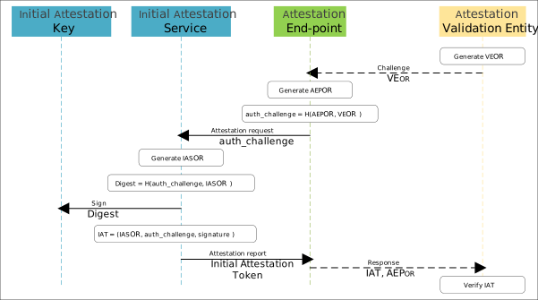
The Validation Entity (VE) uses the metadata in the object record VEORto initiate a challenge to the Attestation End Point (AEP). The content and purpose of this object record depend on the attestation scheme adopted. To ensure the freshness of the data, it is recommended to use a nonce in each challenge. The AEP requests an Initial Attestation Token (IAT) from the Initial Attestation Service, and provides at least the metadata that needs to be verified by the VE under this attestation scheme. Usually, this metadata is the AEP-specific data in the object record AEPORand the cryptographic hash of VEOR.
The Initial Attestation Service constructs the object record IASOR, whose content usually includes:
The boot seed from the Initial Boot State, and the boot state of each updatable component loaded during the secure boot process;
The current security lifecycle state of the system;
The Instance ID and Implementation ID, as well as the calling Partition ID.
The Initial Attestation Key (IAK) is used to sign the cryptographic hash of the data from the AEP and IAS. After the signing is completed with the IAK, the result is returned to the AEP. This signing result is the Initial Attestation Token.
The TF-M Initial Attestation Service exposes the following PSA interfaces:
psa_status_t
psa_initial_attest_get_token(const uint8_t *auth_challenge,
                             size_t         challenge_size,
                             uint8_t       *token_buf,
                             size_t         token_buf_size,
                             size_t        *token_size);

psa_status_t
psa_initial_attest_get_token_size(size_t challenge_size,
                                  size_t *token_size);
These PSA PS interfaces and PS TF-M types are defined and documented in interface/include/psa/initial_attestation.h.in and interface/include/tfm_attest_defs.h, where you can find detailed comments on the interface functions and their usage.
Crypto Service
The TF-M Crypto service is a PRoT service that implements the PSA Certified Crypto API in the PSA RoT secure partition of TF-M. It is based on the Mbed TLS project, which provides a C software library reference implementation of the PSA Crypto API. Other services running in the SPE or applications running in the NSPE can request this service. Its purpose is to provide cryptographic primitives in a secure and efficient manner, which can be implemented in software or by routing the calls to any underlying crypto hardware accelerator or secure element that the platform may provide.
The TF-M Crypto service exposes the PSA interfaces, which are described in detail in the header file interface/include/psa/crypto.h.
This header file itself includes several other header files, which should not be directly included by user applications.
TF-M Configuration
TF-M is automatically compiled and linked in the background as part of the standard Zephyr build process. This build process makes some assumptions about how TF-M is used, and has certain impacts on the functionality of the Zephyr application firmware:
The Secure Processing Environment (secure boot and TF-M) is started first.
The resource allocation of Zephyr depends on the choices made in the secure image.
To add TF-M to the build, you need to add CONFIG_BUILD_WITH_TFM to the prj.conf file to enable the configuration option. You can refer to the related code of Zephyr Sample Projects.
Note
The configuration options related to TF-M in Zephyr are processed in the TF-M module and converted into build options that are passed to the TF-M secure firmware or non-secure firmware.
Kconfig Configuration
Profile Selection
- CONFIG_TFM_PROFILE_TYPE_NOT_SET:
Does not automatically enable any preset service. You need to manually and explicitly configure each secure partition, specify the isolation level, and the runtime model.
- CONFIG_TFM_PROFILE_TYPE_SMALL:
Consists of a lightweight TF-M framework and basic security services to keep the minimum memory footprint, supporting basic security functions on extremely resource-constrained devices.
- CONFIG_TFM_PROFILE_TYPE_MEDIUM:
Securely connects devices to cloud services through asymmetric encryption support. The target devices of Profile Medium need more resources to support more encryption algorithms and higher isolation levels.
- CONFIG_TFM_PROFILE_TYPE_AROTLESS:
Only applicable to devices that do not support Application Root of Trust (ARoT) services. The platform only contains the PSA RoT domain in the SPE, so there is no need to implement isolation between ARoT and PSA RoT. Therefore, this profile selects isolation level 1 to simplify the implementation and optimize the memory footprint and performance.
- CONFIG_TFM_PROFILE_TYPE_LARGE:
Uses isolation level 3 to achieve additional isolation between Application RoT (App RoT) services, selects more encryption algorithms and cipher suites, and can enable basic software defenses against physical attacks.
Note
If CONFIG_TFM_PROFILE_TYPE_NOT_SET is selected, you need to manually configure the isolation level, runtime model, and secure partitions.
Isolation Level
- CONFIG_TFM_ISOLATION_LEVEL:
Three isolation levels, with optional values: 1, 2, 3.
Note
Value description:
Manually set the required TF-M isolation level. The optional values are 1, 2, or 3; the default value is determined by the build configuration.
When using the TF-M Profile option, manually setting the isolation level is not allowed, because it is automatically determined by the Profile setting.
Since isolation levels 2 and 3 require PSA API (TFM IPC) support, level 1 will be forced when TFM IPC is not enabled.
Runtime Model
- CONFIG_TFM_IPC:
Uses the IPC model as the SPM backend of the PSA API. The IPC model supports the IPC and SFN partition models, as well as isolation levels 1, 2, and 3. In this model, each secure partition processes signals in any order, and can delay responding to a message while continuing to process other signals.
- CONFIG_TFM_SFN:
Uses the SFN model as the SPM backend of the PSA API. The SFN model supports the SFN partition model and isolation level 1. In this model, each secure partition consists of a set of callback functions that implement security services.
Secure Partitions
- CONFIG_TFM_PARTITION_PROTECTED_STORAGE:
Protected Storage service.
- CONFIG_TFM_PARTITION_INTERNAL_TRUSTED_STORAGE:
Internal Trusted Storage service.
- CONFIG_TFM_PARTITION_CRYPTO:
Crypto service.
- CONFIG_TFM_PARTITION_INITIAL_ATTESTATION:
Initial Attestation service.
DTS Configuration
The sram0_ns entry is added to the file zephyr/dts/arm/realtek/amebag2/amebag2.dtsi to store the non-secure firmware content, that is, zephyr.bin.
sram0_ns: memory@20025000 {
    compatible = "mmio-sram";
    reg = <TFM_NS_RAM_BASE TFM_NS_RAM_SIZE>;
};
The variant target rtl8721f_evb//ns is built using the configuration in the file zephyr/boards/realtek/rtl8721f_evb/rtl8721f_evb_ns.dts, in which zephyr,sram uses sram0_ns,
and which contains the flash layout partitioning. This is associated with the flash layout introduced in the Flash Layout section; note that they must not conflict.
#include "rtl8721f_evb_common.dts"

/ {
     chosen {
             zephyr,sram = &sram0_ns;
     };
};

&spic {
     status = "okay";
};

/* 4MB flash - TFM BL2 layout
 * BL2 (MCUboot):             0x000000 - 0x040000 (256 KB)
 * S  primary   slot0:        0x040000 - 0x080000 (256 KB)
 * NS primary   slot0_ns:     0x080000 - 0x100000 (512 KB)
 * S  secondary slot1:        0x100000 - 0x140000 (256 KB)
 * NS secondary slot1_ns:     0x140000 - 0x1C0000 (512 KB)
 * PS:          0x256000 - 0x25B000 (20 KB)
 * ITS:         0x25B000 - 0x25F000 (16 KB)
 * OTP/NV:      0x25F000 - 0x261000 (8 KB)
 */
&flash0 {
     reg = <0x04000020 DT_SIZE_M(4)>;

     partitions {
             compatible = "fixed-partitions";
             #address-cells = <1>;
             #size-cells = <1>;

             /* BL2 / MCUboot: 256 KB */
             boot_partition: partition@0 {
                     label = "bootloader";
                     reg = <0x00000000 0x00040000>;
                     read-only;
             };

             /* TFM-S primary (slot0): 256 KB */
             slot0_partition: partition@40000 {
                     label = "image-0";
                     reg = <0x00040000 0x00040000>;
             };

             /* NS primary (slot0_ns): 512 KB */
             slot0_ns_partition: partition@80000 {
                     label = "image-0-nonsecure";
                     reg = <0x00080000 0x00080000>;
             };

             /* TFM-S secondary (slot1): 256 KB */
             slot1_partition: partition@100000 {
                     label = "image-1";
                     reg = <0x00100000 0x00040000>;
             };

             /* NS secondary (slot1_ns): 512 KB */
             slot1_ns_partition: partition@140000 {
                     label = "image-1-nonsecure";
                     reg = <0x00140000 0x00080000>;
             };

             /* Protected Storage: 20 KB */
             tfm_ps_partition: partition@256000 {
                     label = "tfm-ps";
                     reg = <0x00256000 0x00005000>;
             };

             /* Internal Trusted Storage: 16 KB */
             tfm_its_partition: partition@25b000 {
                     label = "tfm-its";
                     reg = <0x0025b000 0x00004000>;
             };

             /* OTP / NV Counters: 8 KB */
             tfm_otp_partition: partition@25f000 {
                     label = "tfm-otp-nv";
                     reg = <0x0025f000 0x00002000>;
             };

             storage_partition: partition@261000 {
                     label = "storage";
                     reg = <0x00261000 0x00006000>;
             };
     };
};
Flash Layout
The flash-layout-related configuration is mainly in the file modules/tee/tf-m/trusted-firmware-m/platform/ext/target/realtek/rtl8721f_evb/partition/flash_layout.h.
The main configuration content is as follows, and the meaning of the configuration is shown in the comments.
/* Size of a Secure and of a Non-secure image */
#define FLASH_S_PARTITION_SIZE          (256 * 1024) /* S partition: 256 KB */
#define FLASH_NS_PARTITION_SIZE         (0x80000) /* NS partition: 512 KB */

/* Sector size of the flash hardware; same as FLASH0_SECTOR_SIZE */
#define FLASH_AREA_IMAGE_SECTOR_SIZE    (0x1000)     /* 4 KB */
/* Same as FLASH0_SIZE */
#define FLASH_TOTAL_SIZE                (0x00400000) /* 4 MB */

/* RTL8721F Flash base address */
#define FLASH_BASE_ADDRESS              (0x08000000)

/* Protected Storage (PS) Service definitions */
#define FLASH_PS_AREA_OFFSET            (0x00256000)
#define FLASH_PS_AREA_SIZE              (0x5000)   /* 20 KB */

/* Internal Trusted Storage (ITS) Service definitions */
#define FLASH_ITS_AREA_OFFSET           (FLASH_PS_AREA_OFFSET + \
                                      FLASH_PS_AREA_SIZE)
#define FLASH_ITS_AREA_SIZE             (0x4000)   /* 16 KB */

/* OTP_definitions */
#define FLASH_OTP_NV_COUNTERS_AREA_OFFSET (FLASH_ITS_AREA_OFFSET + \
                                        FLASH_ITS_AREA_SIZE)
#define FLASH_OTP_NV_COUNTERS_AREA_SIZE   (FLASH_AREA_IMAGE_SECTOR_SIZE * 2)
#define FLASH_OTP_NV_COUNTERS_SECTOR_SIZE FLASH_AREA_IMAGE_SECTOR_SIZE

/* RTL8721F (AmebaG2) memory aliases */
#define S_ROM_ALIAS_BASE  (0x00C00020)  /* Secure Flash base (XIP virtual address, no S-bit prefix) */
#define NS_ROM_ALIAS_BASE (0x04000020)  /* Non-Secure Flash base (same physical flash) */

#define S_RAM_ALIAS_BASE         (SRAM_BL2_START + SRAM_BL2_SIZE) /* 0x2000D000 */

#if defined(TFM_NS_REG_TEST) || defined(TFM_S_REG_TEST)
#define S_DATA_SIZE              (140 * 1024)
#else
#define S_DATA_SIZE              (96 * 1024)
#endif

#define NS_RAM_ALIAS_BASE        (S_RAM_ALIAS_BASE + S_DATA_SIZE)
Note
Regarding the flash layout configuration above, note the following points:
FLASH_TOTAL_SIZEandFLASH_BASE_ADDRESSare fixed according to the chip hardware specification and cannot be modified. Other configurations are based on them and cannot exceed the maximum capacity of the flash.FLASH_S_PARTITION_SIZEandFLASH_NS_PARTITION_SIZEare the spaces allocated to the secure firmware and the non-secure firmware. If the space is insufficient, a build error may occur.The three groups of configurations, PS, ITS, and OTP_NV_COUNTERS, are used by the security services. Note that they must not conflict, to avoid overwriting or trampling each other. The configured addresses are offsets relative to the flash start address.
The
NS_RAM_ALIAS_BASEaddress is the entry address at which the secure firmware jumps to the non-secure firmware in the scenario wheretfm_nsis used as the non-secure firmware. A wrong configuration will cause a wrong jump and a runtime error. Since the secure firmware occupies a large amount of RAM during the regression test,NS_RAM_ALIAS_BASEneeds to be moved backward, but in the normal scenario the secure firmware does not use such a large space, so the regression test macro is used to distinguish them. Note that since the non-secure firmware cannot obtain whether the secure firmware is running the regression test, the secure firmware and the non-secure firmware regression tests are bound and tested together here.
TF-M Build
Build Command
If TrustZone is supported and Zephyr is expected to run in the non-secure environment, use the board target with the corresponding */ns variant when building. The */ns variant enables the Cortex-M Security Extensions (CMSE).
When building a board target without */ns, TF-M is not used.
Note
CONFIG_TRUSTED_EXECUTION_NONSECURE is configured in zephyr/boards/realtek/rtl8721f_evb/rtl8721f_evb_ns_defconfig, and this configuration file is used when building rtl8721f_evb//ns.
The built zephyr.bin is used as the non-secure firmware, and the tfm_s.bin obtained from building TF-M is used as the secure firmware.
An example build command is as follows:
west build -b rtl8721f_evb//ns zephyr/samples/tfm_integration/tfm_ipc
Note
During the build, a script is called for post-processing to merge tfm_s.bin, zephyr.bin, and other firmware to output an amebagreen2_app.bin for flashing. The image used for flashing is in build/images.
For the following intermediate products, if any: the secure firmware build products such as tfm_s.bin can be viewed in build/tfm/bin, the non-secure firmware build products such as tfm_ns.bin can be viewed in build/tfm_ns/bin,
and the zephyr.bin build product is in build/zephyr.
Zephyr Sample Projects
Zephyr integrates several sample projects. These TF-M integration samples can be used with supported Armv8-M boards and demonstrate how to use the TF-M API together with Zephyr.
The TF-M sample and demo project directory is zephyr/samples/tfm_integration, which contains the following projects:
config_build: Tests the ns variant build configuration.
tfm_ipc: Uses IPC to implement communication between the secure image and the non-secure image.
psa_crypto: Uses the PSA Crypto API for encryption and device certificate signing requests.
psa_protected_storage: Uses the Protected Storage (PS) API to store encrypted data.
tfm_secure_partition: Creates a secure partition to expose a security service.
tfm_psa_test: Tests the PSA API. Only one secure partition can be opened for testing at a time. The test code is implemented in
modules/tee/tf-m/psa-arch-tests.tfm_regression_test: TF-M secure firmware and non-secure firmware regression test. The test code is implemented in
modules/tee/tf-m/tf-m-tests.
The first five sample projects use Zephyr as the non-secure firmware, and the last two sample projects use tfm_ns as the non-secure firmware. Although Zephyr is also built, since CONFIG_TFM_USE_NS_APP is configured,
tfm_ns is finally merged into the final bin file used for flashing as the non-secure firmware. The following uses tfm_psa_test as an example to introduce how to use a sample project.
tfm_psa_test
This project uses Zephyr and TF-M to run the PSA (Platform Security Architecture) test suite.
The PSA tests are implemented in the psa-arch-tests repository. This sample only supports platforms that have been ported in psa-arch-tests; rtl8721f_evb has been ported.
Only one test suite can be run at a time, set by one of the following Kconfig options:
CONFIG_TFM_PSA_TEST_CRYPTO — cryptography test
CONFIG_TFM_PSA_TEST_PROTECTED_STORAGE — protected storage test
CONFIG_TFM_PSA_TEST_INTERNAL_TRUSTED_STORAGE — internal trusted storage test
CONFIG_TFM_PSA_TEST_STORAGE — general storage test
CONFIG_TFM_PSA_TEST_INITIAL_ATTESTATION — initial attestation test
Taking CONFIG_TFM_PSA_TEST_STORAGE as an example, you can configure CONFIG_TFM_PSA_TEST_STORAGE=y in prj.conf, or you can add a build option in the build command as follows:
west build -b rtl8721f_evb//ns zephyr/samples/tfm_integration/tfm_psa_test/ -- -DCONFIG_TFM_PSA_TEST_STORAGE=y
Sample output:
10:18:56.394  [BOOT-I] ROM:[V1.0]
10:18:56.396  [BOOT-I] FLASH RATE:1, Pinmux:0
10:18:56.398  [BOOT-I] BOOT FROM NOR
10:18:56.398  [BOOT-I] Boot from Flash
10:18:56.399  [BOOT-I] IMG1(OTA1) Version: 1.1
10:18:56.399  [BOOT-I] IMG1 ENTRY [104005ad:0]
10:18:56.399  [BOOT-I] AP BOOT REASON 0:
10:18:56.399  Initial Power on
10:18:56.399  [BOOT-I] IMG1 ENTER MSP:[30000fc0]
10:18:56.399  [BOOT-I] Build Time: Mar 13 2026 11:46:15
10:18:56.399  [BOOT-I] PMC_CORE_ROLE: KM4NS
10:18:56.399  [PSRAM-I] PSRAM CLK: 400MHz, DQ16, Size: 16MB
10:18:56.399  [BOOT-I] Init APM PSRAM
10:18:56.399  [PSRAM-I] Cal win size 21
10:18:56.399  [PSRAM-I] Cal win size 20
10:18:56.399  [FLASH-I] Flash ID: 85-20-18 (Capacity: 128M-bit)
10:18:56.414  [FLASH-I] Flash Read 4IO
10:18:56.415  [FLASH-I] FLASH CLK: 100000000 Hz
10:18:56.415  [FLASH-I] FLASH HandShake OK
10:18:56.415  [BOOT-I] NP XIP IMG[02000000:33100]
10:18:56.417  [BOOT-I] NP SRAM[20068000:2800]
10:18:56.417  [BOOT-I] NP PSRAM[02035900:20]
10:18:56.417  [BOOT-I] AP XIP IMG[04000000:9ca0]
10:18:56.419  [BOOT-I] AP SRAM[20027000:680]
10:18:56.419  [BOOT-I] AP PSRAM[0400a320:20]
10:18:56.421  [BOOT-I] AP IMG3[10c00000:1a760]
10:18:56.421  [BOOT-I] AP NSC[20006000:23c0]
10:18:56.421  [BOOT-W] IMG3 not encrypted! Enable RDP for MP!
10:18:56.421  [BOOT-W] IMG3 not encrypted! Enable RDP for MP!
10:18:56.423  [BOOT-W] IMG3 not encrypted! Enable RDP for MP!
10:18:56.423  [BOOT-W] IMG3 not encrypted! Enable RDP for MP!
10:18:56.423  [BOOT-W] IMG3 not encrypted! Enable RDP for MP!
10:18:56.425  [BOOT-I] IMG2 BOOT from OTA 1, Version: 1.1
10:18:56.425  [CHIPINFO-W] PSRAM or DRAM End in layout is 0x60400000, but actually is 0x61000000
10:18:56.425  set MPC using actually value
10:18:56.427  [BOOT-I] Start NonSecure @ 0x4cc9b3bb ...
10:18:56.427  [APP-I] NP CPU CLK: 240000000 Hz
10:18:56.427  Booting TF-M v2.2.0+g47f6dda
10:18:56.429  [WRN] This device was provisioned with dummy keys. This device is NOT SECURE
10:18:56.429  [MAIN-I] IWDG refresh thread Started!
10:18:56.429  [Sec Thread] Secure image initializing!
10:18:56.430  [MAIN-I] NP OS START
10:18:56.434  [INF][PS] Encryption alg: 0x5500100
10:18:56.434  [INF][Crypto] Provision entropy seed...
10:18:56.434  [INF][Crypto] Provision entropy seed... complete.
10:18:56.489  Non-Secure system starting...
10:18:56.493  ***** PSA Architecture Test Suite - Version 1.4 *****
10:18:56.493
10:18:56.493  Running.. Storage Suite
10:18:56.493  ******************************************
10:18:56.493
10:18:56.493  TEST: 401 | DESCRIPTION: UID not found check | UT: STORAGE
10:18:56.493  [Info] Executing tests from non-secure
10:18:56.502
10:18:56.502  [Info] Executing ITS tests
10:18:56.502  [Check 1] Call get API for UID 6 which is not set
10:18:56.502  [Check 2] Call get_info API for UID 6 which is not set
10:18:56.502  [Check 3] Call remove API for UID 6 which is not set
10:18:56.621  [Check 4] Call get API for UID 6 which is removed
10:18:56.621  [Check 5] Call get_info API for UID 6 which is removed
10:18:56.623  [Check 6] Call remove API for UID 6 which is removed
10:18:56.623  Set storage for UID 6
10:18:56.662  [Check 7] Call get API for different UID 5
10:18:56.662  [Check 8] Call get_info API for different UID 5
10:18:56.662  [Check 9] Call remove API for different UID 5
10:18:56.744
10:18:56.746  [Info] Executing PS tests
10:18:56.747  [Check 1] Call get API for UID 6 which is not set
10:18:56.747  [Check 2] Call get_info API for UID 6 which is not set
10:18:56.747  [Check 3] Call remove API for UID 6 which is not set
10:18:57.951  [Check 4] Call get API for UID 6 which is removed
10:18:57.964  [Check 5] Call get_info API for UID 6 which is removed
10:18:57.964  [Check 6] Call remove API for UID 6 which is removed
10:18:57.967  Set storage for UID 6
10:18:58.364  [Check 7] Call get API for different UID 5
10:18:58.364  [Check 8] Call get_info API for different UID 5
10:18:58.364  [Check 9] Call remove API for different UID 5
10:18:59.175
10:18:59.175  TEST RESULT: PASSED
10:18:59.175
10:18:59.175  ******************************************
...
10:19:21.898  TEST: 417 | DESCRIPTION: Storage assest capacity modification check | UT: STORAGE
10:19:21.898  [Info] Executing tests from non-secure
10:19:21.901
10:19:21.901  [Info] Executing PS tests
10:19:21.905  Test Case skipped as Optional PS APIs not are supported.
10:19:21.905
10:19:21.905  TEST RESULT: SKIPPED (Skip Code=0x0000002B)
10:19:21.905
10:19:21.905  ******************************************
10:19:21.914
10:19:21.916  ************ Storage Suite Report **********
10:19:21.916  TOTAL TESTS     : 17
10:19:21.921  TOTAL PASSED    : 11
10:19:21.923  TOTAL SIM ERROR : 0
10:19:21.925  TOTAL FAILED    : 0
10:19:21.927  TOTAL SKIPPED   : 6
10:19:21.929  ******************************************
10:19:21.931
10:19:21.935  Entering standby..
Note
Although
CONFIG_TFM_PROFILE_TYPE_LARGE=yis set in theprj.confof the tfm_psa_test sample project, theCMakeLists.txtadds the-DTFM_ISOLATION_LEVEL=2build option, so the secure firmware actually runs at isolation level 2.Both the tfm_psa_test and tfm_regression_test sample projects build
tfm_nsat the end of theirCMakeLists.txt, which requiresHAL_REALTEK. It is automatically downloaded during the build, but the downloaded repository content may not be the latest. You can also use an existing path by adding the-DHAL_REALTEK_PATH=${ZEPHYR_HAL_REALTEK_MODULE_DIR}build option.In the tfm_regression_test sample project, the secure regression test and the non-secure regression test must be enabled at the same time, because the regression test occupies a large amount of SRAM, and a separate flash layout is provided for it.
In the tfm_regression_test sample project, when
TFM_BL2is not enabled, you need to remove-DQCBOR_PATH${QCBOR_PATH_TYPE}=${CONFIG_TFM_QCBOR_PATH}from theCMakeLists.txtin the project directory to automatically downloadqcbor; otherwise, passing an empty value will not download it.TFM_QCBOR_PATHis included byTFM_BL2. IfTFM_BL2is not enabled, the configuration does not take effect, and the value ofTFM_QCBOR_PATHis empty.The tfm_ipc sample project is configured with
CONFIG_TFM_PROFILE_TYPE_NOT_SET=yandCONFIG_TFM_IPC=y, so it runs at isolation level 1. You need to configureCONFIG_TFM_PROFILE_TYPE_MEDIUM=yorCONFIG_TFM_ISOLATION_LEVEL=2to make it run at isolation level 2.The
ITSandPSsecure partition services use flash. The related tests may require erasing the flash first, to avoid residual values affecting the usage during runtime.
Adding a Secure Partition
A secure partition is an execution environment that provides the following functions for Root of Trust (RoT) services:
Acquiring resources and protecting its own code and data.
A mechanism to interact with other components in the system.
Each secure partition is an independent execution thread and is the smallest unit of isolation.
This section mainly introduces how to add a secure partition in TF-M, focusing on the configuration, manifest, and implementation rules. The actual source-code-level implementation is not included in this document.
Process
The main steps for adding a secure partition are as follows:
Adding a Source Folder
Add a source folder for the new secure partition under the <TF-M base folder>/secure_fw/partitions directory (assume the folder name is example):
This folder should contain the following parts:
Manifest file
CMake configuration file
Source code file
Adding a Manifest
Each secure partition must declare its resource requirements in a manifest file. The Secure Partition Manager (SPM) uses the manifest file to assemble and allocate resources within the secure partition (SPE). The manifest file contains the following content:
Secure partition name
List of implemented RoT services
Access to other RoT services
Memory requirements
Scheduling hints
Peripheral memory-mapped I/O regions and interrupts
Note
Users can set the priority attribute in the secure partition manifest to LOW, NORMAL, or HIGH.
The manifest tool tools/tfm_parse_manifest_list.py calculates the loading priority of a secure partition based on its priority value and its dependencies. During TF-M initialization, the SPM determines the loading and initialization order of secure partitions based on their loading priority values.
A secure partition with a higher
priorityis loaded and initialized before a secure partition with a lowerpriority.A secure partition is loaded and initialized only after its dependencies have been loaded and initialized.
The following is a manifest reference example for the IPC model:
{
  "psa_framework_version": 1.1,
  "name": "TFM_SP_EXAMPLE",
  "type": "APPLICATION-ROT",
  "priority": "NORMAL",
  "model": "IPC",
  "entry_point": "tfm_example_main",
  "stack_size": "0x0200",
  "services" : [
    {
      "name": "ROT_A",
      "sid": "0x000000E0",
      "non_secure_clients": true,
      "connection_based": true,
      "version": 1,
      "version_policy": "STRICT"
      "mm_iovec": "disable"
    }
  ],
  "mmio_regions": [
    {
      "name": "TFM_PERIPHERAL_A",
      "permission": "READ-WRITE"
    }
  ],
  "irqs": [
    {
      "source": "TFM_A_IRQ",
      "name": "A_IRQ",
      "handling": "SLIH"
    }
  ]
  "dependencies": [
    "TFM_CRYPTO",
    "TFM_INTERNAL_TRUSTED_STORAGE_SERVICE"
  ]
}
Note
To use the SFN model, users need to replace "model": "IPC" with "model": "SFN". Users also need to remove the "entry_point" attribute, and can optionally replace it with "entry_init".
Updating the Manifest List
<TF-M base folder>/tools/tfm_manifest_list.yaml and tools/tfm_parse_manifest_list.py are used to collect the necessary information required by the secure partitions. The manifest tool processes this information and generates the necessary files during the build process.
Reference configuration example:
{
  "description": "TFM Example Partition",
  "manifest": "secure_fw/partitions/example/tfm_example_partition.yaml",
  "conditional": "@TFM_PARTITION_EXAMPLE@",
  "output_path": "partitions/example",
  "version_major": 0,
  "version_minor": 1,
  "pid": 290,
  "linker_pattern": {
    "library_list": [
      "*tfm_*partition_example*"
     ]
  }
}
TF-M also supports building external secure partitions, in which you can have your own manifest list. For details, see Out-of-tree secure partition build.
Secure Partition ID Distribution
Each secure partition has an identifier (ID). TF-M generates a header file containing the secure partition ID definitions. This header file is located at <TF-M build folder>generated/interface/include/psa_manifest/pid.h.
Each definition uses the name attribute in the manifest as its name, and its value is assigned by the SPM.
The partition ID can be set to a fixed value, or omitted to be assigned automatically.
#define name id-value
Secure Partition |
PID range |
|---|---|
TF-M internal partitions |
0 - 255 |
PSA and user partitions |
256 - 2999 |
TF-M test partitions |
3000 - 4999 |
Firmware framework test partitions | 5000 - 5999 |
|
Reserved |
6000 - |
Refer to the files <TF-M base folder>/tools/tfm_manifest_list.yaml, <TF-M extras repo>/partitions/*/*_manifest_list.yaml, <TF-M test repo>/tests_reg/test/secure_fw/tfm_test_manifest_list.yaml,
and <TF-M test repo>/tests_psa_arch/spe/tfm_psa_ff_test_manifest_list.yaml for detailed PID allocation information.
For where to add the definition, see the Updating the Manifest List section.
RoT Service ID (SID) Distribution
An RoT service is identified by its RoT service ID (SID). The SID is a 32-bit number associated with a symbolic name in the secure partition manifest. Bits 31 to 12 uniquely identify the vendor of the RoT service. The remaining bits 11 to 0 can be used at the vendor’s discretion.
The following is the RoT service ID table used in TF-M.
Secure Partition |
Vendor ID (20-bit) |
Function ID (12-bit) |
|---|---|---|
initial_attestation |
0x00000 |
0x020-0x03F |
platform |
0x00000 |
0x040-0x05F |
protected_storage |
0x00000 |
0x060-0x06F |
internal_trusted_storage |
0x00000 |
0x070-0x07F |
crypto |
0x00000 |
0x080-0x09F |
firmware_update |
0x00000 |
0x0A0-0x0BF |
tfm_secure_client |
0x0000F |
0x000-0x01F |
tfm_ipc_client |
0x0000F |
0x060-0x07F |
tfm_ipc_service |
0x0000F |
0x080-0x09F |
tfm_slih_test_service |
0x0000F |
0x0A0-0x0AF |
tfm_flih_test_service |
0x0000F |
0x0B0-0x0BF |
tfm_ps_test_service |
0x0000F |
0x0C0-0x0DF |
tfm_secure_client_2 |
0x0000F |
0x0E0-0x0FF |
tfm_sfn_test_service_1 |
0x0000F |
0x100-0x11F |
tfm_sfn_test_service_2 |
0x0000F |
0x120-0x13F |
tfm_attest_test_service |
0x0000F |
0x140-0x15F |
RoT Service Stateless Handle Distribution
A secure partition can contain stateless services. These services are distinguished and referenced by stateless handles. In the manifest file, a stateless_handle attribute is set to index the stateless service. In the current implementation,
this attribute must be "auto" or a number in the range [1, 32], and can be extended. In addition, for a stateless service, the connection-based attribute must be set to false.
The index of the stateless handle is divided into two ranges for different purposes. Indexes [1, 16] are allocated to TF-M secure partitions. The remaining indexes [17, 32] are reserved for any other secure partitions, such as those in tf-m-tests and tf-m-extras.
The following table summarizes the stateless handle allocation of TF-M secure partitions.
Partition Name |
Stateless Handle |
|---|---|
TFM_SP_CRYPTO |
1 |
TFM_SP_PS |
2 |
TFM_SP_ITS |
3 |
TFM_SP_INITIAL_ATTESTATION |
4 |
TFM_SP_FWU |
5 |
TFM_SP_PLATFORM |
6 |
stack_size
The stack_size attribute is used to indicate the stack memory usage of the secure partition. The value of this attribute must be a decimal or hexadecimal value in bytes. It can also be a build-configurable item,
whose default value is defined in the configuration config_base.cmake. This configuration value can be overridden to adapt to different usage scenarios.
heap_size
This attribute is optional, with a default value of 0. It indicates the heap memory usage of the secure partition. The allowed values are the same as those of stack_size.
mmio_regions
This attribute is a list of MMIO region objects that the secure partition needs to access. TF-M currently only supports named_region. Users need to provide a name macro to indicate the variable of the memory region.
TF-M uses the following structure to represent peripheral memory.
struct platform_data_t {
  uint32_t periph_start;
  uint32_t periph_limit;
  int16_t periph_ppc_bank;
  int16_t periph_ppc_loc;
};
Note
The TF-M protocol does not expect to use this structure; this is just what the current implementation adopts. Other peripherals that require different information to implement isolation need to define a structure with the same name but different content.
The following is an example:
struct platform_data_t tfm_peripheral_A;
#define TFM_PERIPHERAL_A                 (&tfm_peripheral_A)
mm_iovec
Memory-Mapped IOVEC (MM-IOVEC) provides direct mapping of the client’s input and output vectors to the secure partition. If this attribute is set to enable, the secure partition can use the MM-IOVEC API when the framework supports MM-IOVEC.
Using MM-IOVEC can provide memory and runtime optimization for larger buffers, but it reduces the mitigation capability against common security vulnerabilities. Whether to use MM-IOVEC depends on the requirements for memory and runtime optimization as well as security.
Updating the Build System
To accommodate the newly added secure partition, the following changes need to be made to the build system.
Adding a CMakeLists.txt File
Each secure partition must have a corresponding CMakeLists.txt, in this case <TF-M base folder>/secure_fw/partitions/example/CMakeLists.txt, which is the build configuration for this secure partition.
The following is a reference example of a CMakeLists.txt.
The CMake file should contain the following content:
Add the library file
tfm_app_rot_partition_exampleand the related source files.add_library(tfm_app_rot_partition_example STATIC) target_sources(tfm_app_rot_partition_example PRIVATE tfm_example_partition.c )
Note
A secure partition must be compiled as an independent static library, and the name of the library must follow the following pattern, because it affects how the linker script places the partition in memory:
Use
tfm_psa_rot_partition*in the case of a PSA RoT partition.Use
tfm_app_rot_partition*in the case of an ARoT partition.
Add the source files generated by the manifest tool.
# The intermedia file defines the partition stack.
target_sources(tfm_app_rot_partition_example
    PRIVATE
        ${CMAKE_BINARY_DIR}/generated/example_partition/auto_generated/intermedia_tfm_example_partition.c
)

# The load info file includes the static data of the partition.
target_sources(tfm_partitions
    INTERFACE
        ${CMAKE_BINARY_DIR}/generated/example_partition/auto_generated/load_info_tfm_example_partition.c
)
Add dependencies using the manifest tool.
To ensure that the above generated files are up to date when building the secure partition library, a dependency between the library and the manifest tool target should be set.
add_dependencies(tfm_app_rot_partition_example manifest_tool)
Link the
tfm_sprtinterface for the PSA API.target_link_libraries(tfm_app_rot_partition_example PRIVATE tfm_sprt )
Link the secure partition library to
tfm_partitionsso that it is included in the final image.target_link_libraries(tfm_partitions INTERFACE tfm_app_rot_partition_example )
Finally, the build of this secure partition should be added to <TF-M base folder>/secure_fw/partitions/CMakeLists.txt.
add_subdirectory(example)
Updating the Configuration System
If the secure partition has a build configuration to enable or disable it, this configuration option should be added to the configuration system.
CMake Configuration
The default value of the configuration option should be added to <TF-M base folder>/config/config_base.cmake.
set(TFM_PARTITION_EXAMPLE OFF CACHE BOOL "Enable the example partition")
Kconfig Configuration
A menuconfig should be added to <TF-M base folder>/secure_fw/partitions/example/Kconfig.
menuconfig TFM_PARTITION_EXAMPLE
    bool "Enable the Example Partition"
    default n
And add it to <TF-M base folder>/secure_fw/partitions/Kconfig.
rsource "example/Kconfig"
Note
If the secure partition is not enabled, the secure partition build process should be skipped. This can be achieved by adding the following code at the beginning of its CMakeLists.txt.
if (NOT TFM_PARTITION_EXAMPLE)
    return()
endif()
Implementing RoT Services
To implement an RoT service, the partition needs a source file that contains the implementation of the service and the partition entry point. Users can create this source file under <TF-M base folder>/secure_fw/partitions/example/tfm_example_partition.c.
The following example implements an RoT service ROT_A with a SID.
IPC Model Partition Entry Point
After the secure partition is initialized, this function must have a loop that repeatedly waits for input signals and then processes these signals.
#include "psa_manifest/tfm_example.h"
#include "psa/service.h"

void tfm_example_main(void)
{
    psa_signal_t signals = 0;

    /* Secure Partition initialization */
    example_init();

    /*
     * Continually wait for one or more of the partition's RoT Service or
     * interrupt signals to be asserted and then handle the asserted
     * signal(s).
     */
    while (1) {
        signals = psa_wait(PSA_WAIT_ANY, PSA_BLOCK);
        if (signals & ROT_A_SIGNAL) {
            rot_A();
        } else {
            /* Should not come here */
            psa_panic();
        }
    }
}
SFN Model Partition Entry Initialization
In the SFN model, a secure partition contains an optional initialization function, which is declared as the entry_init symbol mentioned in the Adding a Manifest section. After initialization, the entry_init function returns the following values:
Returns
PSA_SUCCESSif the initialization is successful.Returns
PSA_SUCCESSif the initialization is partially successful and some SFNs are expected to receive messages. A non-running RoT service must respond to connection requests withPSA_ERROR_CONNECTION_REFUSED.Returns an error status if the initialization fails, and no SFN within the secure partition may be called.
IPC Model Service Implementation
The service is implemented by a function rot_A(), which is called when an incoming signal is received. The specific implementation is up to the user, but we provide a sample service for reference.
The following example sends the message “Hello World” when called.
#include "psa_manifest/tfm_example.h"
#include "psa/service.h"

/* Some other type of services. */
#define SOME_ROT_A_SERVICE_TYPE                (1)

static void rot_A(void)
{
    const int BUFFER_LEN = 32;
    psa_msg_t msg;
    int i;
    uint8_t rec_buf[BUFFER_LEN];
    uint8_t send_buf[BUFFER_LEN] = "Hello World";

    psa_get(ROT_A_SIGNAL, &msg);
    switch (msg.type) {
    case PSA_IPC_CONNECT:
    case PSA_IPC_DISCONNECT:
        /*
         * This service does not require any setup or teardown on connect
         * or disconnect, so just reply with success.
         */
        psa_reply(msg.handle, PSA_SUCCESS);
        break;
    default:
        /* Handling services requested by psa_call. */
        if (msg.type == PSA_IPC_CALL) {
            for (i = 0; i < PSA_MAX_IOVEC; i++) {
                if (msg.in_size[i] != 0) {
                    psa_read(msg.handle, i, rec_buf, BUFFER_LEN);
                }
                if (msg.out_size[i] != 0) {
                    psa_write(msg.handle, i, send_buf, BUFFER_LEN);
                }
            }
            psa_reply(msg.handle, PSA_SUCCESS);
        } else if (msg.type == SOME_ROT_A_SERVICE_TYPE) {
            /* Operations for SOME_ROT_A_SERVICE_TYPE */
        } else {
            /* Invalid type for this Secure Partition. */
            return PSA_ERROR_PROGRAMMER_ERROR;
        }
    }
}
SFN Model Service Implementation
The SFN model consists of a set of Secure Functions (SFN), one SFN for each RoT service. Connection, disconnection, and request messages do not cause the SFN secure partition to assert a secure partition signal. Instead, the Secure Function (SFN) corresponding to the RoT service is called by the framework, and the message details are passed to that SFN as parameters. To add a Secure Function (SFN) for each RoT service to handle messages, each SFN will have the following prototype.
psa_status_t <<name>>_sfn(const psa_msg_t *msg);
The following includes a connection-based sample service for reference, which sends the message “Hello World” when called.
#include "psa_manifest/tfm_example.h"
#include "psa/service.h"

/* Some other type of services. */
#define SOME_ROT_A_SERVICE_TYPE                (1)

psa_status_t rot_a_sfn(const psa_msg_t *msg)
{
    const int BUFFER_LEN = 32;
    int i;
    uint8_t rec_buf[BUFFER_LEN];
    uint8_t send_buf[BUFFER_LEN] = "Hello World";

    switch (msg->type) {
    case PSA_IPC_CONNECT:
    case PSA_IPC_DISCONNECT:
        /*
         * This service does not require any setup or teardown on connect
         * or disconnect, so just reply with success.
         */
        return PSA_SUCCESS;
    default:
        /* Handling services requested by psa_call. */
        if (msg->type == PSA_IPC_CALL) {
            for (i = 0; i < PSA_MAX_IOVEC; i++) {
                if (msg->in_size[i] != 0) {
                    psa_read(msg->handle, i, rec_buf, BUFFER_LEN);
                }
                if (msg->out_size[i] != 0) {
                    psa_write(msg->handle, i, send_buf, BUFFER_LEN);
                }
            }
            return PSA_SUCCESS;
        } else if (msg->type == SOME_ROT_A_SERVICE_TYPE) {
            /* Operations for SOME_ROT_A_SERVICE_TYPE */
        } else {
            /* Invalid type for this Secure Partition. */
            return PSA_ERROR_PROGRAMMER_ERROR;
        }
    }
}
Out-of-Tree Secure Partition Build
TF-M supports building external secure partitions whose source code folders are maintained outside the TF-M code repository. Developers can configure TFM_EXTRA_MANIFEST_LIST_FILES and TFM_EXTRA_PARTITION_PATHS on the build command line to include external secure partitions.
TFM_EXTRA_MANIFEST_LIST_FILESA list of absolute paths to the manifest lists provided by the external secure partitions. Multiple manifest lists are separated by a semicolon
;. Multiple manifest lists are enclosed in double quotes.TFM_EXTRA_PARTITION_PATHSA list of absolute directories of the source code folders of the external secure partitions. The TF-M build system searches for
CMakeLists.txtin the partition source code folders. Multiple external secure partition directories are separated by a semicolon;. Multiple directories are enclosed in double quotes.
A single external secure partition folder can be organized as follows.
secure partition folder
      ├── CMakeLists.txt
      ├── manifest_list.yaml
      ├── out_of_tree_partition_manifest.yaml
      └── source code
In the above example, TFM_EXTRA_MANIFEST_LIST_FILES and TFM_EXTRA_PARTITION_PATHS in the build command are configured as follows.
-DTFM_EXTRA_MANIFEST_LIST_FILES=<Absolute-path-sp-folder/manifest_list.yaml>
-DTFM_EXTRA_PARTITION_PATHS=<Absolute-path-sp-folder>
Multiple external secure partitions can adopt different organizational structures. For example, multiple secure partitions can be maintained under the same directory, as shown below.
top-level folder
      ├── Partition 1
      │       ├── CMakeLists.txt
      │       ├── partition_1_manifest.yaml
      │       └── source code
      ├── Partition 2
      │       └── ...
      ├── Partition 3
      │       └── ...
      ├── manifest_list.yaml
      └── Root CMakeLists.txt
In the above example, the root CMakeLists.txt file includes the CMakeLists.txt files of all partitions, for example through add_subdirectory(). The manifest_list.yaml lists the manifest files of all partitions.
TFM_EXTRA_MANIFEST_LIST_FILES and TFM_EXTRA_PARTITION_PATHS on the build command line are configured as follows.
-DTFM_EXTRA_MANIFEST_LIST_FILES=<Absolute-path-top-level-folder/manifest_list.yaml>
-DTFM_EXTRA_PARTITION_PATHS=<Absolute-path-top-level-folder>
Alternatively, the out-of-tree secure partitions can be placed in different folders.
partition 1 folder                    partition 2 folder
    ├── CMakeLists.txt                    ├── CMakeLists.txt
    ├── manifest_list.yaml                ├── manifest_list.yaml
    ├── partition_1_manifest.yaml         ├── partition_2_manifest.yaml
    └── source code                       └── source code
In the above example, each secure partition manages its own manifest file and CMakeLists.txt file. TFM_EXTRA_MANIFEST_LIST_FILES and TFM_EXTRA_PARTITION_PATHS on the build command line can be configured as follows. Note that these inputs need to be enclosed in double quotes.
-DTFM_EXTRA_MANIFEST_LIST_FILES="<Absolute-path-part-1-folder/manifest_list.yaml>;<Absolute-path-part-2-folder/manifest_list.yaml>"
-DTFM_EXTRA_PARTITION_PATHS="<Absolute-path-part-1-folder>;<Absolute-path-part-2-folder>"
Note
The manifest lists in the TFM_EXTRA_MANIFEST_LIST_FILES paths do not need to correspond one-to-one with the secure partition directories in TFM_EXTRA_PARTITION_PATHS. The order also does not matter.
TFM_EXTRA_MANIFEST_LIST_FILES and TFM_EXTRA_PARTITION_PATHS can be configured in multiple additional source files. It is recommended to use the CMake list APPEND method to avoid accidental overwriting.
Additional Notes
In the Inter-Process Communication (IPC) model, the memory access mechanism proposed by PSA FF is used. The SPM provides APIs and isolation boundary checks; free access to memory may cause a program crash.
In the Inter-Process Communication (IPC) model, memory checks inside the partition runtime are unnecessary. The SPM handles the memory checks when the memory access API is called.
In the IPC model, the client ID is already included in the message structure, and the secure partition can obtain the ID by calling the
psa_get()function. Therefore, the secure partition no longer needs to manually calltfm_core_get_caller_client_id()to obtain the caller’s client ID.In the Inter-Process Communication (IPC) model, the Secure Partition Manager (SPM) checks the security policy and partition dependencies between the client and the service. Therefore, the service no longer needs to verify the identity of the secure caller.