Wi-Fi R-Mesh Introduction
Wi-Fi R-Mesh Topology
As shown in the figure below, Wi-Fi R-Mesh is a tree-topology mesh network used to increase the Wi-Fi coverage, allowing stations that are far from the AP to also obtain a stable network connection.

Wi-Fi R-Mesh topology
Wi-Fi R-Mesh Advantage
The well-designed Wi-Fi R-Mesh has the following advantages:
A software-unsensible mesh network:
All Mesh protocols are implemented at Wi-Fi driver layer. Both root nodes and child nodes are regarded by the application as standard Wi-Fi stations connected to the AP.
No updates are required for Wi-Fi configuration programs.
Rapid pairing and switching within microseconds:
Child nodes can quickly switch to a new parent node with better signal quality without interrupting data communication.
If the parent node encounters a problem (such as power off or hang), the child node can rapidly detect the issue and switch to an alternative parent node without interrupting data communication.
A node can migrate all its child nodes to a new parent node while maintaining uninterrupted data flow.
High throughput across multiple hops:
R-Mesh forwarding bypasses the TCP/IP protocol stack, operating directly at the driver layer, utilizing less RAM and MCU resources.
With extremely short software processing time, better throughput can be achieved.
Network stability:
Simplified software architecture eliminates complex routing table algorithms, ensuring network stability.
Traditional mesh network issues like loops do not occur.
Wi-Fi R-Mesh Data Flow
Wi-Fi R-Mesh handles data forwarding directly at the Wi-Fi driver layer, requiring less RAM and MCU resources.
Due to the minimal software processing involved, nodes maintain good throughput even after several hops.

Wi-Fi R-Mesh data flow
Wi-Fi R-Mesh Capacity
The capacity of Wi-Fi R-Mesh refers to the maximum number of child nodes that can be connected to a root node.
The Wi-Fi R-Mesh topology diagram illustrates an example where the capacity is 4. Each root node can support up to 4 child nodes regardless of the topology.
Topology 0: All child nodes are directly connected to the root node.
Topology 3: The four nodes form a 4-hop linear network.
Can also be any other topologies between Topology 0 and Topology 3
The capacity of Wi-Fi R-Mesh is 4
The capacity of Wi-Fi R-Mesh is 32
Wi-Fi R-Mesh NAT (R-NAT)
In the R-Mesh network, each node establishes a real Wi-Fi connection with the AP. Consequently, the number of nodes that R-Mesh can support is constrained by the limited capacity of stations the AP can connect to.
To handle this limitation, we can implement a station + SoftAP solution based on the Network Address Translation (NAT) protocol to expand the number of nodes in R-Mesh. In this solution, the root node and its child nodes are connected to the SoftAP, rather than directly to the AP. The NAT protocol handles data forwarding between the AP network and the R-Mesh network.
In R-Mesh, such nodes are referred to as R-NAT nodes.
As illustrated in the figure below, the R-NAT node is positioned between the root node and the AP to extend the number of nodes that can access the network.

Wi-Fi R-NAT
Wi-Fi R-Mesh Throughput
Throughput Test
Similar to the regular Station or AP mode, we can test the throughput of R-Mesh via iperf command. As shown in the diagram below, simply input the iperf commands on the PC at the AP side and the node side.

R-Mesh throughput test
At R-Mesh node side, input the following AT command via UART:
AT+IPERF=-c,<server IP>,-i,<periodic>,-u,-b,<bandwidth>,-t,<transtime>,-p,<port>
At AP side (normally a PC), input the following iperf command via Terminal:
iperf -s -i <periodic> -u -p <port>
At R-Mesh node side, input the following AT command via UART:
AT+IPERF=-s,-i,<periodic>,-u,-p,<port>
At AP side (normally a PC), input the following iperf command via Terminal:
iperf -c <R-mesh node IP> -i <periodic> -u -b <bandwidth> -t <transtime> -p <port>
At R-Mesh node side, input the following AT command via UART:
AT+IPERF=-c,<server IP>,-i,<periodic>,-t,<transtime>,-p,<port>
At AP side (normally a PC), input the following iperf command via Terminal:
iperf -s -i <periodic> -p <port>
At R-Mesh node side, input the following AT command via UART:
AT+IPERF=-s,-i,<periodic>,-p,<port>
At AP side (normally a PC), input the following iperf command via Terminal:
iperf -c <R-mesh node IP> -i <periodic> -t <transtime> -p <port>
Throughput
The throughput data of Wi-Fi R-Mesh is shown in the following table:
(Single Node indicates nodes at each hierarchical level conduct TP testing separately; L1 + L2 indicates L1 and L2 nodes conduct TP testing simultaneously; Other scenarios follow the same pattern)
Test scenario |
Layer |
UDP Tx (Mbps) |
UDP Rx (Mbps) |
TCP Tx (Mbps) |
TCP Rx (Mbps) |
|---|---|---|---|---|---|
Single Node |
Layer1 |
54.2 |
39.5 |
17.0 |
15.7 |
Layer2 |
19.6 |
18.8 |
9.6 |
10.0 |
|
Layer3 |
12.8 |
11.6 |
6.9 |
7.0 |
|
Layer4 |
9.4 |
8.2 |
5.4 |
5.2 |
|
Layer5 |
7.5 |
6.2 |
4.4 |
4.3 |
|
L1 + L2 |
Layer1 |
21.0 |
21.2 |
||
Layer2 |
12.5 |
14.0 |
|||
L1 + L2 + L3 |
Layer1 |
14.0 |
13.3 |
||
Layer2 |
7.0 |
7.2 |
|||
Layer3 |
5.1 |
6.4 |
|||
L1 + L2 + L3 + L4 |
Layer1 |
10.0 |
12.1 |
||
Layer2 |
4.0 |
8.4 |
|||
Layer3 |
3.6 |
6.7 |
|||
Layer4 |
3.0 |
4.0 |
|||
L1 + L2 + L3 + L4 + L5 |
Layer1 |
9.0 |
10.4 |
||
Layer2 |
3.2 |
3.7 |
|||
Layer3 |
2.5 |
2.9 |
|||
Layer4 |
2.3 |
1.8 |
|||
Layer5 |
1.8 |
2.1 |
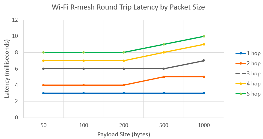
Wi-Fi R-Mesh RTT
Unlike BLE and ZigBee, R-Mesh has a very low Round-Trip Time (RTT) and and it does not significantly increase even as packet size increases.
Wi-Fi R-Mesh Memory Size
Enabling R-Mesh will consume additional memory of the following size:
Item |
KM0 |
|---|---|
txt |
22KB |
rodata |
2.4KB |
data+bss |
0.9KB |
heap |
20KB |