Audio Recorder
Resources
Introduction
Audio Recorder is designed by Realtek to set up the audio configurations of Ameba chip, capture the audio data from Ameba chip and record it to PCM/WAV file.
The GUI of Audio Recorder is shown in the following figure.
Environment Setup
Hardware Setup
Connect the UART port on Ameba chip to USB port on PC via USB to UART dongle, as illustrated in the following figure.

Note
The UART port for audio record is implementation related, adjust it as per the HW/SW design.
Choose a proper USB to UART dongle to meet the requirement of the desired audio data rate.
Software Setup
PC environment: Win 7 or later, Microsoft .NET Framework 4.0
Ameba environment: image with audio record demo
Chip Setup
Edit the Chip.json file located in the same directory of Audio Recorder executable file to set up the chip configurations.
[
   {
      "ChipID": "RTL872XD",
      "BaudRate": 3000000,
      "AmicNum": 2,
      "DmicNum": 3,
      "MinRefNum": 1,
      "MaxRefNum": 1
   },
   {
      "ChipID": "RTL8720E",
      "BaudRate": 3000000,
      "AmicNum": 3,
      "DmicNum": 4,
      "MinRefNum": 1,
     "MaxRefNum": 2
   },
   {
      "ChipID": "RTL8730A",
      "BaudRate": 3000000,
      "AmicNum": 5,
      "DmicNum": 8,
      "MinRefNum": 1,
      "MaxRefNum": 2
   }
]
The chip configurations are organized as a list of chip info, the description of chip info is as below:
Configuration |
Type |
Description |
|---|---|---|
ChipID |
string |
The ID to identify the chip, can be freely changed as required |
BaudRate |
int |
The baud rate of the serial port for audio record, HW/SW implementation related |
AmicNum |
int |
Number of AMIC interfaces, HW implementation related |
DmicNum |
int |
Number of DMIC interfaces, HW implementation related |
MinRefNum |
int |
Minimum number of REF channels, HW/SW implementation related |
MaxRefNum |
int |
Maximum number of REF channels, HW/SW implementation related |
Audio Setup
Setup with GUI
Audio Recorder allows user to set up the most frequently used audio configurations from GUI:
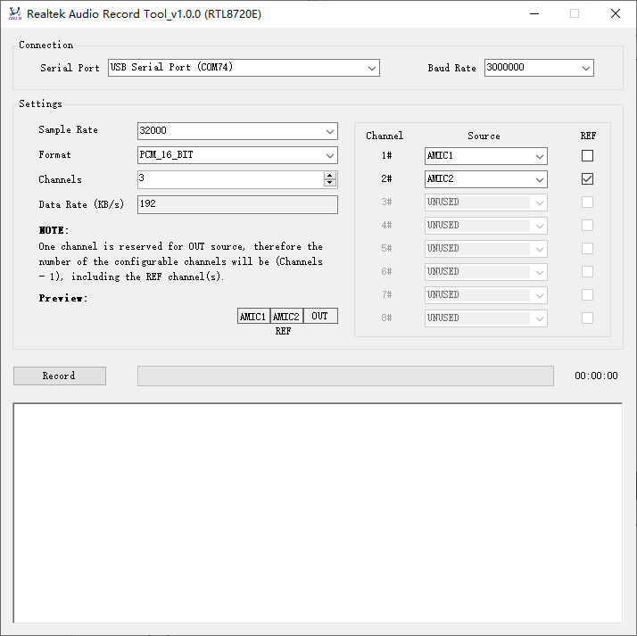
And the GUI configurations are described as below:
Configuration |
Description |
|---|---|
Serial Port |
Serial port, select the exact serial port for audio record. |
Baud Rate |
Baud rate for serial port. |
Sample Rate |
Audio sample rate. |
Format |
Audio format, valid values correspond to the Ameba SW implementation. |
Channels |
Audio channels, valid values range from 3 to 9. One channel is reserved for OUT source, therefore the number of configurable channels will be (Channels - 1). |
Source |
Audio source, AMICs and DMICs, the available sources are limited by AmicNum and DmicNum in Chip.json. |
REF |
Reference channel, the number of reference channels is limited by MinRefNum and MaxRefNum in Chip.json. |
A real-time preview will be provided as per the configurations of Channels, Source and REF.
Setup with Configuration File
After the first time startup, a file named Settings.json will be generated the same directory of Audio Recorder executable file, saving the runtime record configurations. And this file will be updated each time after Audio Recorder has been closed.
Settings.json holds more configurations than GUI, and its format is shown as below:
{
   "Config": {
      "Channels": [
         65281,
         130818,
         65535,
         65535,
         65535,
         65535,
         65535,
         65535
      ],
      "SampleRate": 32000,
      "Format": "PCM_16_BIT",
      "DeviceType": "RTPIN_IN_MIC",
      "ChannelCount": 3
   },
   "ChipID": "RTL8720E",
   "SerialPort": "USB Serial Port (COM74)",
   "SerialBaudRate": 3000000,
   "SerialDataBits": 8,
   "SerialStopBits": "One",
   "SerialParity": "None",
   "SerialRxBufferLength": 32768,
   "DataRateThreshold": 90,
   "DataPayloadLength": 1440,
   "DataBufferLength": 4194304,
   "MaxRxDataLength": 4294967295,
   "GenWavFile": false
}
User is allowed to edit this file to adjust the record configurations:
Configuration |
Type |
Description |
UI Configuration |
|---|---|---|---|
ChipID |
string |
The ID to identify the chip, shall correspond to the ChipID in Chip.json. |
N/A |
SerialPort |
string |
Serial port name. |
Serial Port |
SerialBaudRate |
int |
Serial port baud rate. |
Baud Rate |
SerialDataBits |
int |
Serial port data bits, Ameba SW implementation related. |
N/A |
SerialStopBits |
enum |
Serial port stop bits, valid values correspond to Ameba SW implementation:
|
N/A |
SerialParity |
enum |
Serial port parity, valid values correspond to Ameba SW implementation:
|
N/A |
SerialRxBufferLength |
int |
Serial port RX buffer length. |
N/A |
DataRateThreshold |
int |
A threshold in percentage to limited the audio data rate as per serial port baud rate. The audio data rate shall not be larger than: (baud rate * SerialDataBits / (1 + SerialDataBits + SerialStopBits) / 1000) * DataRateThreshold / 100 KB/s Otherwise, Audio Recorder will pop up a warning dialog and refuse to start record when user clicks the Record button. |
N/A |
DataPayloadLength |
int |
The data payload length in byte of the data packet sent from Ameba to Audio Recorder on PC, Ameba SW implementation related. |
N/A |
DataBufferLength |
int |
Data buffer length in byte for Audio Recorder to save the received audio data at runtime |
N/A |
MaxRxDataLength |
u64 |
Maximum RX data length in byte for Audio Recorder to record audio data to a data file. For WAV files, limited by the WAV spec, MaxRxDataLength shall be less than 4GB (0x100000000). While for PCM files, there is no 4GB limitation. |
N/A |
GenWavFile |
bool |
Indicates whether to save the record data as WAV file: true: WAV file (.wav) false: raw PCM file (.pcm) |
N/A |
Config -> Channels |
list<u32> |
Maximum 9 channels are supported with at most 8 configurable channels and 1 OUT channel, the configurable channel is defined as below: bit 0: AMIC 1 bit 1: AMIC 2 bit 2: AMIC 3 … bit 7: AMIC 8 bit 8: DMIC 1 bit 9: DMIC 2 bit 10: DMIC 3 … bit 15: DMIC 8 bit 16: REF bit 17~bit 31: reserved Specially, bit 0~7 = 0b11111111 indicates AMIC is unused while bit 8~15 = 0b11111111 indicates DMIC is unused. E.g. 0b11111111100000010 represents AMIC2 as REF. |
Source & REF |
Config -> SampleRate |
int |
Audio sample rate, the max value is limited by Ameba HW/SW implementation. |
Sample Rate |
Config -> Format |
enum |
Audio format, valid values correspond to Ameba SW implementation:
|
Format |
Config -> DeviceType |
enum |
Device type, valid values correspond to Ameba SW implementation:
|
N/A |
Config -> ChannelCount |
int |
Channel count, the max value is limited by Ameba HW implementation. |
Channels |
Note
For the changes to be effective, Settings.json shall be modified only when Audio Recorder is closed, otherwise, any changes will be overwrote when closing Audio Recorder.
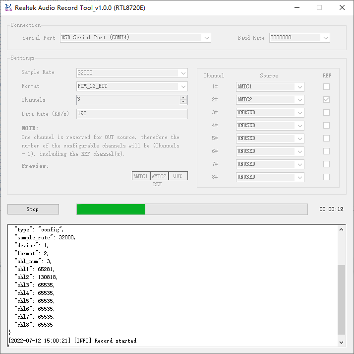
Audio Record
Start Record
After configuration, click the “Record” button to start the record.
If configuration is illegal, a warning dialog will pop up and record will be refused, user shall adjust the configurations and retry.
If configuration is OK, record will be started.
During the record processing:
The elapsed record time will be updated by second.
The progress bar will keep on turning circles, with 60 second for a circle.
Log message will be printed to the text box, indicating key information, warnings and errors.
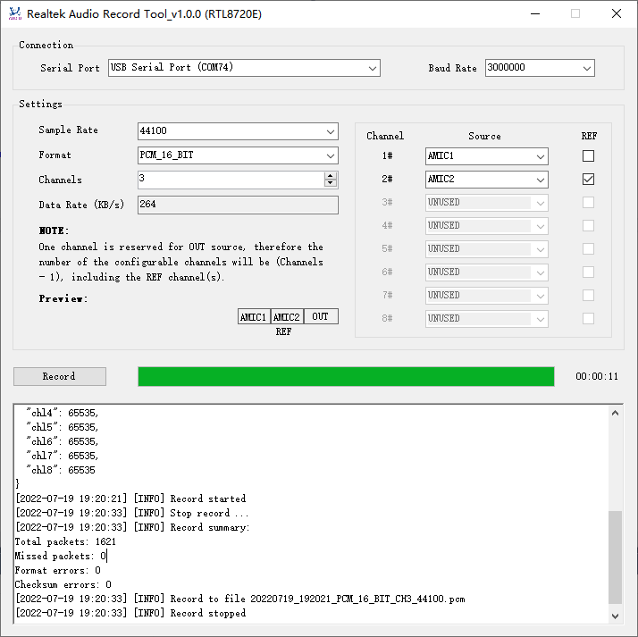
Stop Record
When Audio Recorder is recording, click the “Stop” button will stop the record.
The record data will be saved as a PCM file or a WAV file specified by GenWavFile property in Setting.json, located in the log directory under the directory of Audio Recorder executable file, and the file name will be printed in the log text box, with following naming rule:
<Timestamp>_<Format>_CH<Channels>_<Sample Rate>.<FileType>
For example:
20220719_192021_PCM_16_BIT_CH3_44100.pcm

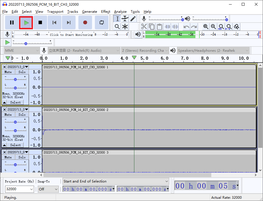
Audio Play
The generated audio file can be played with multi-track audio player, e.g. use to play the generated PCM file:
File -> Import -> Raw Data
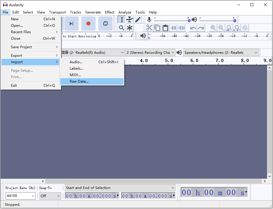
Select the generated PCM file and set up audio configurations as per the record configurations on Audio Recorder:
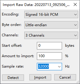
The audio configurations are described as below:
Configuration |
Description |
|---|---|
Encoding |
Audio encoding, shall correspond with Format configuration on Audio Recorder |
Byte order |
Endian, choose Little-endian |
Channels |
Channels, shall correspond with Channels configuration on Audio Recorder |
Start offset |
Start offset, default 0 |
Amount to import |
Amount to import, default 100 |
Sample rate |
Sample rate, shall correspond with Sample Rate configuration on Audio Recorder |
Click the play button: