Linux USB Introduction
Overview
Universal Serial Bus Plug and Play (USB OTG) is initially supported by the Linux USB subsystem, combined with Realtek’s custom USB PHY driver and certain modifications to the DWC2 USB controller driver.
Architecture
The USB software architecture is shown below.
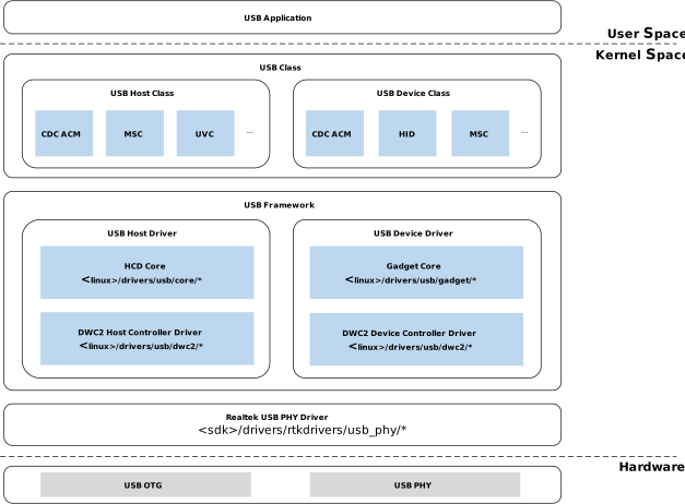
USB Software Stack Layers
The following table shows the complete USB software stack layers from hardware to application:
Layer |
Component |
Description |
|---|---|---|
Application Layer |
|
User-space tools and test scripts |
Class Driver |
|
Protocol handling for each USB class |
USB Core Layer |
|
Enumeration, transfer management, UDC framework |
Controller Driver |
|
Host/Device dual-role controller (Realtek modified) |
PHY Driver |
|
Realtek USB PHY, clock/calibration/force_mode |
Hardware Layer |
USB Controller ( |
RTL8730E USB OTG peripheral |
Implementation
File |
Description |
|---|---|
<linux>/drivers/usb/dwc2/ |
DWC2 host and device controller driver modified by Realtek |
<linux>/drivers/usb/core/ |
HCD core |
<linux>/drivers/usb/gadget/ |
Gadget core |
<linux>/drivers/usb/gadget/function/ |
Device classes, e.g. ADB, CDC ACM, HID, MSC, etc. |
<linux>/drivers/usb/class/cdc-acm.* |
CDC ACM host class |
<linux>/drivers/usb/storage/* |
MSC host class |
<linux>/drivers/media/usb/uvc/ |
UVC host class |
<linux>/sound/usb/ |
UAC host class (snd-usb-audio) |
<linux>/drivers/rtkdrivers/usb_phy/ |
Realtek USB PHY driver |
Refer to usb system v5.4 or usb system v6.18 for more details on the USB subsystem.
Configuration
USB Device Tree Configuration
The USB device tree node is defined in sources/kernel/linux-6.18/arch/arm/boot/dts/realtek/ameba/rtl8730e-ocp.dtsi:
usb: usb@40080000 {
   reg = <0x40080000 0x20000>;
   interrupts = <GIC_SPI 39 IRQ_TYPE_LEVEL_HIGH>;
   g-rx-fifo-size = <504>;
   g-np-tx-fifo-size = <256>;
   g-tx-fifo-size = <256>;
   status = "okay";
   endpoints {
      ep1in {
         ep_name = "ep1in";
         ep_type = <0x0E>; // USB_EP_CAPS_TYPE_ALL
      };
      ep2out {
         ep_name = "ep2out";
         ep_type = <0x0E>; // USB_EP_CAPS_TYPE_ALL
      };
      ep3in {
         ep_name = "ep3in";
         ep_type = <0x0E>; // USB_EP_CAPS_TYPE_ALL
      };
      ep4out {
         ep_name = "ep4out";
         ep_type = <0x0E>; // USB_EP_CAPS_TYPE_ALL
      };
      ep5in {
         ep_name = "ep5in";
         ep_type = <0x0E>; // USB_EP_CAPS_TYPE_ALL
      };
      ep5out {
         ep_name = "ep5out";
         ep_type = <0x0E>; // USB_EP_CAPS_TYPE_ALL
      };
   };
};
The device tree configuration for USB is shown below:
Property |
Description |
Configurable? |
|---|---|---|
compatible |
ID used to match the DWC2 controller driver with the USB OTG device. |
No |
reg |
USB register resources |
No |
interrupts |
GIC interrupt for USB |
No |
g-rx-fifo-size |
Periodic receive FIFO size for USB device (in DWORDS). |
16~512 |
g-np-tx-fifo-size |
Non-periodic transmit FIFO size for USB device (in DWORDS). |
16~256 |
g-tx-fifo-size |
Array of TX FIFO sizes in dedicated FIFO mode. Each value corresponds to a starting endpoint (in DWORDS). Realtek USB operates in shared FIFO mode, so this configuration is ignored. |
16~256 |
status |
USB device status |
disabled/okay |
endpoints |
Allows USB endpoint address configuration to meet specific customer requirements. |
Yes |
Note
The total data FIFO depth is 1016, meaning the sum of g-rx-fifo-size, g-np-tx-fifo-size, and g-tx-fifo-size should not exceed 1016.
Do not change the default configuration unless absolutely necessary.
The USB node is enabled by default. To disable it, the node status can be overridden to disabled via node reference in a higher-level device tree file, such as the chip-specific or board-specific device tree file:
&usb{
   status = "disabled";
};
To configure the operating mode, override dr_mode in the board-level device tree file
(e.g. sources/kernel/linux-6.18/arch/arm/boot/dts/realtek/ameba/xx.dts):
&usb {
   dr_mode = "otg";
};
dr_mode controls how the DWC2 driver is initialized:
"host"— Host mode only. Gadget (device) functionality is permanently disabled at driver initialization. Use only when gadget mode is not needed."peripheral"— Device mode only. Host functionality is permanently disabled at driver initialization. Use only when host mode is not needed."otg"(default) — Both roles initialized. On QFN100, useforce_modeto specify the role manually. See DRD.
Compile Configuration
USB features can be configured as either built-in features in the kernel firmware or as separate kernel modules.
The following built-in and module configurations are mutually exclusive options; choose according to your actual requirements.
Config Item |
menuconfig Path |
|---|---|
USB PHY driver |
|
USB support |
|
USB Gadget Support |
|
Support for Host-side USB |
|
DesignWare USB2 DRD Core Support |
|
DWC2 mode (host mode shown as example) |
|
Note
Select the DWC2 mode according to your actual requirements:
Host mode:
(*) Host only modeDevice mode:
( ) Gadget only modeOTG mode:
( ) Dual Role USB support
[*] USB support must be selected to enter the USB submenu.
The USB PHY driver is located under Device Drivers -> Drivers for Realtek.
Config Item |
menuconfig Path |
|---|---|
USB PHY driver |
|
USB support |
|
USB Gadget Support |
|
Support for Host-side USB |
|
DesignWare USB2 DRD Core Support |
|
DWC2 mode (host mode shown as example) |
|
Note
DWC2 mode selection is the same as for built-in configuration. Module loading must be done in order:
Host mode:
insmod /lib/modules/<kernel_ver>/kernel/drivers/rtkdrivers/usb_phy/phy-rtk-usb.ko
insmod /lib/modules/<kernel_ver>/kernel/drivers/usb/common/usb-common.ko
insmod /lib/modules/<kernel_ver>/kernel/drivers/usb/core/usbcore.ko
insmod /lib/modules/<kernel_ver>/kernel/drivers/usb/gadget/udc/udc-core.ko
insmod /lib/modules/<kernel_ver>/kernel/drivers/usb/roles/roles.ko
insmod /lib/modules/<kernel_ver>/kernel/drivers/usb/dwc2/dwc2.ko
Device mode:
insmod /lib/modules/<kernel_ver>/kernel/drivers/rtkdrivers/usb_phy/phy-rtk-usb.ko
insmod /lib/modules/<kernel_ver>/kernel/drivers/usb/common/usb-common.ko
insmod /lib/modules/<kernel_ver>/kernel/drivers/usb/core/usbcore.ko
insmod /lib/modules/<kernel_ver>/kernel/drivers/usb/gadget/udc/udc-core.ko
insmod /lib/modules/<kernel_ver>/kernel/fs/configfs/configfs.ko
insmod /lib/modules/<kernel_ver>/kernel/drivers/usb/gadget/libcomposite.ko
insmod /lib/modules/<kernel_ver>/kernel/drivers/usb/roles/roles.ko
insmod /lib/modules/<kernel_ver>/kernel/drivers/usb/dwc2/dwc2.ko
Quick Start
The SDK provides an on-board script /bin/rtk_usb_test.sh for quickly testing USB functionality.
Before using rtk_usb_test.sh, ensure the corresponding kernel options are enabled.
Refer to the configuration sections below for menuconfig paths.
The table below lists all USB classes supported by the usb system v6.18 , their current defconfig status, and whether they are supported by rtk_usb_test.sh.
Class |
Kernel CONFIG |
defconfig Status |
rtk_usb_test.sh |
|---|---|---|---|
CDC ACM Host |
|
not set |
Y |
Mass Storage Host |
|
=m |
Y |
UVC Host |
|
not set |
Y |
HID Host |
|
=m |
Y |
UAC Host |
|
not set |
Y |
Vendor-Specific Host |
|
not set |
Y |
USB Serial |
|
not set |
N |
UAS |
|
not set |
N |
CDC Networking Host (ECM / NCM / RNDIS / EEM) |
|
not set |
N |
Others (Printer / WDM / TMC / Bluetooth / USB Monitor / EHSET) |
|
not set |
N |
Class |
Kernel CONFIG |
defconfig Status |
rtk_usb_test.sh |
|---|---|---|---|
CDC ACM Device |
|
=y |
Y |
Mass Storage Device |
|
=y |
Y |
HID Device |
|
=y |
Y |
UAC2 Device |
|
not set |
Y |
ADB Device |
|
=y |
Y |
Vendor-Specific Device |
|
=y |
Y |
USB OTG (Dual Role) |
|
=y |
Y |
UVC Gadget |
|
not set |
N |
Network Gadget (ECM / RNDIS / NCM) |
|
not set |
N |
UAC1 Gadget |
|
not set |
N |
FunctionFS |
|
not set |
N |
Serial Gadget (gser) |
|
not set |
N |
Others (UAC1 Legacy / MIDI / MIDI2 / Printer / TCM / OBEX / EEM / Phonet) |
|
not set |
N |
Note
Enabling all supported class features simultaneously may cause the rootfs firmware image to overflow. Please select only the features currently needed according to your actual project requirements.
“Others” rows include classes that are available in the kernel source but are not commonly used in embedded/IoT scenarios. They are listed here for reference only. Enable via menuconfig if needed.
Usage:
Use the -r parameter specifies the role to test (e.g., usbh_msc, usbh_uac, usbd_acm, usbd_hid, etc.). This command automatically loads the kernel modules required for the corresponding feature and automatically
sets the USB mode (host or device).
sh /bin/rtk_usb_test.sh -r <role>
For features already compiled into the kernel, use the -b parameter to skip module loading:
sh /bin/rtk_usb_test.sh -b -r <role>