WHC Interface and Hardware Configuration
WHC Hardware Configuration
WHC Interface Connections
The pin connections between Ameba and Raspberry Pi are as follows:
Interface |
SoC pin |
Function |
|---|---|---|
SDIO |
PB6 |
SDIO_DAT2 |
PB7 |
SDIO_DAT3 |
|
PB8 |
SDIO_CMD |
|
PB9 |
SDIO_CLK |
|
PB13 |
SDIO_DAT0 |
|
PB14 |
SDIO_DAT1 |
|
SPI |
PB24 |
SPI_MOSI |
PB25 |
SPI_MISO |
|
PB23 |
SPI_CLK |
|
PB26 |
SPI_CS |
|
PB8 |
DEV_TX_REQ |
|
PB9 |
DEV_READY |
Interface |
SoC pin |
Function |
|---|---|---|
SDIO |
PA4 |
SDIO_DAT2 |
PA21 |
SDIO_DAT3 |
|
PA19 |
SDIO_CMD |
|
PA18 |
SDIO_CLK |
|
PA5 |
SDIO_DAT0 |
|
PA20 |
SDIO_DAT1 |
|
SPI |
PA30 |
SPI_MOSI |
PA31 |
SPI_MISO |
|
PA29 |
SPI_CLK |
|
PB0 |
SPI_CS |
|
PA19 |
DEV_TX_REQ |
|
PA18 |
DEV_READY |
Interface |
Raspberry Pi |
Function |
|---|---|---|
SDIO |
GPIO 26 |
SDIO_DAT2 |
GPIO 27 |
SDIO_DAT3 |
|
GPIO 23 |
SDIO_CMD |
|
GPIO 22 |
SDIO_CLK |
|
GPIO 24 |
SDIO_DAT0 |
|
GPIO 25 |
SDIO_DAT1 |
|
SPI |
GPIO 10 |
SPI_MOSI |
GPIO 9 |
SPI_MISO |
|
GPIO 11 |
SPI_CLK |
|
GPIO 8 |
SPI_CS |
|
GPIO 23 |
DEV_TX_REQ |
|
GPIO 22 |
DEV_READY |
|
UART |
GPIO 14 |
UART_TX |
GPIO 15 |
UART_RX |
Note
SPI DEV_TX_REQ: Ameba notifies Host of pending data transmission via rising edge on this pin
SPI DEV_READY: Ameba status indicator
High level (1): Device ready to receive data
Low level (0): Device busy (pause transmission)
Note
Default SDIO pins defined in Ameba SDK are used. If modification is required, adjust the SDIO_Pin_Grp parameter in the files below, which corresponds to the pinmux index in SDIO_PAD :
file location:
component/soc/usrcfg/amebadplus/ameba_intfcfg.cfile location:
component/soc/usrcfg/amebagreen2/ameba_intfcfg.cHost-side SDIO interrupt requirements:
By default, SDIO_DATA1 is used.
If the Host does not support SDIO interrupts:
It can switch to polling mode for communication.
If the Host requires GPIO-based interrupts: The Ameba platform provides limited configurable GPIOs for this functionality. For detailed configurations and supported GPIO lists, currently request, please contact us.
WHC SDIO Adapter Board
Realtek provides adapter board that enables convenient connection to mini SD card slots. It is recommended to use dedicated adapter boards for interfacing with SDIO pins.
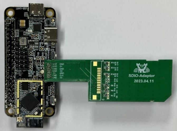
FullMAC SDIO adapter board (physical diagram)
Note
Realtek official adapter boards will be available soon. Currently request samples, please contact us.
WHC Raspberry Pi Direct Connection
For high-speed scenarios, directly solder Ameba SDIO pins to Raspberry Pi GPIO.
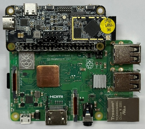
Ameba-Raspberry Pi direct connection diagram