Supported Chips
Overview
MJPEG is a decoder that integrates a JPEG decoder and a post-processor. The JPEG decoder and post-processor can work in standalone mode or combined mode.
In standalone mode, the JPEG decoder and post-processor work independently:
The JPEG decoder decodes input baseline interleaved JPEG format images into YCbCr format data and outputs to memory.
The post-processor can process YCbCr format data in memory, and after processing, output YCbCr or RGB format data to memory.
In combined mode, the data decoded by the JPEG decoder is sent directly to the post-processing unit for processing, and then YCbCr or RGB format data is output to memory.
The MJPEG architecture diagram is as follows:

JPEG Decoder
The JPEG decoder can work in standalone mode or in combined mode with the post-processor. The JPEG decoder has the following features:
Input format: Baseline interleaved JPEG images using YCbCr400, YCbCr420, YCbCr422, YCbCr440, YCbCr411, YCbCr444 sampling formats.
Output format:
Semi-planar raster scan YCbCr420, YCbCr422, YCbCr440, YCbCr411, YCbCr444 formats.
YCbCr400 format with only luminance component
Supports three working modes: normal mode, input buffer mode, and slice mode. Among them, slice mode can only work in standalone mode.
Note
If the input image width and height are not multiples of 16, the JPEG decoder will round up and output data with resolution in multiples of 16 for width and height. The extra parts will be filled with 0 data on the right and bottom of the image.
The JPEG decoder cannot support JPEG images that use different quantization tables for luminance and chrominance components.
Working Modes
The JPEG decoder can work in the following three modes:
Normal mode: The JPEG decoder takes the entire image as input and decodes it into complete YCbCr format data output. Refer to the raw_jpegdec_standalone_normal example (JPEG decoder standalone mode) and raw_combined_normal example (combined mode) for usage.
Input Buffer mode: The JPEG decoder inputs and decodes the image in multiple times. This mode can save input buffer size and reduce decoding delay caused by waiting for the complete JPEG image. Refer to raw_combined_input_buffer example (combined mode) for usage.
Slice mode: The JPEG decoder takes the entire image as input and decodes it into YCbCr format data output in segments. This mode can save output buffer size. Refer to raw_jpegdec_standalone_slice example (JPEG decoder standalone mode) for usage.
Note
Slice mode can only work in JPEG decoder standalone mode.
Slice mode uses the macroblock method for block output. In the raw_jpegdec_standalone_slice example, the input image is an 800x480 resolution YCbCr422 format image. There are 480 / 8 = 60 macroblocks in the vertical direction. If SliceMb is set to 10, it will output in 6 times.
Input Buffer mode calculates the number of decoding times by dividing the JPEG image size by the buffer size.

API Reference
API |
Description |
|---|---|
JpegDecInit |
Initialize JPEG decoder instance |
JpegDecGetImageInfo |
Perform preliminary software decoding and get JPEG image information |
JpegDecDecode |
Perform hardware decoding of JPEG image |
JpegDecRelease |
Release JPEG decoder instance |
Post-processor
The post-processor can work in standalone mode or in combined mode with the JPEG decoder.
Features
The post-processor supports various image processing functions:
Supports multiple input data formats. Refer to Input Data Formats
Supports multiple output data formats. Refer to Output Data Formats
Supports specific rotation functions. This function is only supported in standalone mode. Refer to Rotation
Supports scaling. Refer to Scaling
Supports multiple standard YCbCr to RGB color format conversion standards. Refer to Color Conversion Standards
Supports image enhancement functions. Refer to Image Enhancement
Supports image cropping and picture-in-picture functions. Refer to Cropping and Picture-in-Picture
Supports mask areas and alpha blending areas. Refer to Mask Areas and Alpha Blending
Input Data Formats
The input data sources for the post-processor can be:
Specific YCbCr format data in memory (standalone mode).
Any format data output from the JPEG decoder (combined mode).
In standalone mode, the post-processor supports the following data formats:
Semi-planar raster scan YCbCr420
Semi-planar block layout (16x16) YCbCr420
Planar YCbCr420
YCbYCr 4:2:2, YCrYCb 4:2:2
CbYCrY 4:2:2, CrYCbY 4:2:2
Output Data Formats
The post-processor supports the following output data formats:
Semi-planar YCbCr420
YCbYCr 4:2:2 progressive scan or 4x4 block layout
YCbYCr 4:2:2 progressive scan or 4x4 block layout
YCbYCr 4:2:2 progressive scan or 4x4 block layout
YCbYCr 4:2:2 progressive scan or 4x4 block layout
RGB 32-bit
RGB 16-bit
For RGB output formats, the bit width and position of the alpha channel and color channels are configurable, so color formats such as ARGB8888, RGB565, ARGB4444 can be configured.
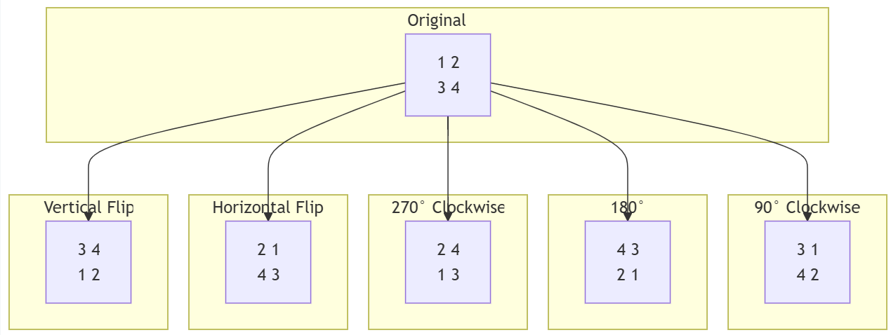
Rotation
The post-processor supports 90, 180, 270 degree rotations and vertical, horizontal flips.
Note
The post-processor only supports rotation and flipping in standalone mode, and cannot use other features at the same time. Refer to the raw_pp_standalone_rotation example for usage.
Scaling
The post-processor’s scaling function uses four-tap horizontal kernels and two-tap vertical kernels for bicubic polynomial interpolation, achieving good scaling results. The scaling function has the following limitations:
Can only scale in the same direction, i.e. either enlarge or reduce both horizontally and vertically.
Maximum enlargement factor is 3.
Color Conversion Standards
When converting YCbCr format data to RGB format data, the post-processor can choose from multiple standards:
BT.601-5 specification
BT.709 specification
User-defined conversion parameters
The conversion formula is as follows, where the user needs to provide parameters a, b, c, d, e.
Image Enhancement
The post-processor provides 4 image enhancement functions: dithering, brightness adjustment, saturation adjustment, and contrast adjustment.
Cropping and Picture-in-Picture
The post-processor can perform rectangular cropping on the original image, allowing selection of crop width, height, and coordinates. It can also output the original image to a larger background image, making the original image part of the background image to achieve picture-in-picture functionality.

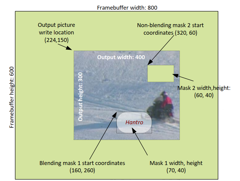
Mask Areas and Alpha Blending
The post-processor provides two rectangular mask areas. These two mask areas can:
Be placed anywhere on the original image
Be selected as mask function, i.e. the original image is not output in the mask area.
Be selected as alpha blending function, i.e. alpha blending can be performed between the original image and input data, with the original image as the bottom layer.
The following figure is an example where mask2 acts as a mask area, partially masking the original image to reveal the background color. Mask1 acts as an alpha blending area, performing alpha blending between the input data and the original image.
Note
The upper layer data for alpha blending comes from memory and can only be in the following formats:
8-bit alpha value + YCbCr444 (8 bits per component)
ARGB8888
Divisibility Requirements for Post-processor Parameters
Parameter |
YCbCr420 |
YCbCr422 |
RGB 16bit |
RGB 32bit |
|---|---|---|---|---|
Input image width and height |
16 |
16 |
16 |
16 |
Cropped image width and height |
8 |
8 |
8 |
8 |
Cropped image coordinates |
16 |
16 |
16 |
16 |
Output image width |
2 |
2 |
1 |
1 |
Output image height |
2 |
1 |
1 |
1 |
Mask area width and X coordinate |
2 |
2 |
1 |
1 |
Mask area height and Y coordinate |
2 |
1 |
1 |
1 |
Background image area width and X coordinate of image on background |
8 |
4 |
4 |
2 |
Background image area height and Y coordinate of image on background |
2 |
1 |
1 |
1 |
API Reference
API |
Description |
|---|---|
PPInit |
Initialize post-processor instance |
PPDecCombinedModeEnable |
Enable combined mode |
PPGetConfig |
Initialize post-processor configuration |
PPSetConfig |
Set post-processor configuration |
PPGetResult |
Get post-processor processing results |
PPDecCombinedModeDisable |
Disable combined mode |
PPRelease |
Release post-processor instance |
PPConfig Structure
Use this structure to configure various functions of the post-processor.
Member |
Application |
|---|---|
PPInImage ppInImg; |
Input image parameters |
PPInCropping ppInCrop; |
Input image cropping parameters |
PPInRotation ppInRotation; |
Input image rotation parameters |
PPOutImage ppOutImg; |
Output image parameters |
PPOutRgb ppOutRgb; |
Output image RGB parameters |
PPOutMask1 ppOutMask1; |
Mask area 1 parameters |
PPOutMask2 ppOutMask2; |
Mask area 2 parameters |
PPOutFrameBuffer ppOutFrmBuffer; |
Frame buffer writing parameters |
Application Examples
The SDK provides application examples to help developers understand and use MJPEG functionality:
raw examples
Path:
{SDK}\component\example\peripheral\raw\MJPEG\{demo}Demonstrates how to use MJPEG
Here’s a brief description of the example functionalities:
raw_jpegdec_standalone_normal : Demonstrates the JPEG decoder working in standalone mode in normal mode, decoding a JPEG image into YCbCr format data.
raw_jpegdec_standalone_slice : Demonstrates the JPEG decoder working in standalone mode in slice mode, decoding a JPEG image into YCbCr format data.
raw_pp_standalone_rotation : Demonstrates the post-processor working in standalone mode, rotating a YCbCr format data by 90 degrees.
raw_combined_normal : Demonstrates decoding a JPEG image into RGB 32-bit data in combined mode, without any processing on the image itself.
raw_combined_multi_function <https://github.com/Ameba-AIoT/ameba-rtos/tree/master/component/example/peripheral/raw/MJPEG/raw_combined_multi_function>: Demonstrates in combined mode, decoding a JPEG image into RGB 32-bit data, performing cropping, scaling, masking, alpha blending, brightness adjustment, picture-in-picture, and other processing on the image.
raw_combined_input_buffer: Demonstrates in combined mode, the JPEG decoder working in input buffer mode, decoding a JPEG image into RGB format data.
Example Analysis
Example raw_combined_normal
void combined_normal(void)
{
   JpegDecInst jpegInst = NULL;
   JpegDecRet jpegRet;
   JpegDecImageInfo imageInfo;
   JpegDecInput jpegIn;
   JpegDecOutput jpegOut;
   JpegDecLinearMem input;
   PPInst pp = NULL;
   PPResult ppRet;
   PPConfig pPpConf;

   _memset(&jpegIn, 0, sizeof(JpegDecInput));
   _memset(&jpegOut, 0, sizeof(JpegDecOutput));
   _memset(&imageInfo, 0, sizeof(JpegDecImageInfo));
   _memset(&pPpConf, 0, sizeof(PPConfig));

   RCC_PeriphClockCmd(APBPeriph_MJPEG, APBPeriph_MJPEG_CLOCK, ENABLE);              /* Enable MJPEG clock */
   hx170dec_init();                                                                 /* Initialize low-level driver */

   jpegRet = JpegDecInit(&jpegInst);                                                /* Initialize JPEG instance */
   if (jpegRet != JPEGDEC_OK) {
      RTK_LOGS(NOTAG, RTK_LOG_ERROR, "JpegDecInit error: %d\n", jpegRet);
      goto end;
   } else {
      RTK_LOGS(NOTAG, RTK_LOG_INFO, "JpegDecInit OK\n");
   }

   input.pVirtualAddress = (u32 *) 422_jpeg;
   input.busAddress = (u32) 422_jpeg;
   jpegIn.streamBuffer.pVirtualAddress = (u32 *) input.pVirtualAddress;             /* Configure JPEG image address */
   jpegIn.streamBuffer.busAddress = input.busAddress;
   jpegIn.streamLength = 422_jpeg_len;                                              /* Configure JPEG image size */
   jpegIn.bufferSize = 0;                                                           /* Do not use input buffer mode */

   jpegRet = JpegDecGetImageInfo(jpegInst, &jpegIn, &imageInfo);                    /* Get image info through software decoding */
   if (jpegRet != JPEGDEC_OK) {
      RTK_LOGS(NOTAG, RTK_LOG_ERROR, "JpegDecGetImageInfo error: %d\n", jpegRet);
      goto end;
   }

   ppRet = PPInit(&pp);                                                             /* Initialize post-processor instance */
   if (ppRet != PP_OK) {
      RTK_LOGS(NOTAG, RTK_LOG_ERROR, "PPInit error: %d\n", ppRet);
      goto end;
   }

   ppRet = PPDecCombinedModeEnable(pp, jpegInst, PP_PIPELINED_DEC_TYPE_JPEG);       /* Enable combined mode */
   if (ppRet != PP_OK) {
      RTK_LOGS(NOTAG, RTK_LOG_ERROR, "PPDecCombinedModeEnable error: %d\n", ppRet);
      goto end;
   }

   ppRet = PPGetConfig(pp, &pPpConf);                                                 /* Initialize post-processor configuration parameters */
   if (ppRet != PP_OK) {
      RTK_LOGS(NOTAG, RTK_LOG_ERROR, "PPGetConfig error: %d\n", ppRet);
      goto end;
   }

   pPpConf.ppInImg.width = imageInfo.outputWidth;                                     /* Set post-processor input width to JPEG decoder output width */
   pPpConf.ppInImg.height = imageInfo.outputHeight;                                   /* Set post-processor input height to JPEG decoder output height */
   pPpConf.ppInImg.pixFormat = PP_PIX_FMT_YCBCR_4_2_2_SEMIPLANAR;                     /* Set image to 422 format (can also be determined by JPEG decoder output format) */
   pPpConf.ppOutImg.width = pPpConf.ppInImg.width;                                     /* Set post-processor output width same as input width */
   pPpConf.ppOutImg.height = pPpConf.ppInImg.height;                                   /* Set post-processor output height same as input height */
   pPpConf.ppOutImg.pixFormat = PP_PIX_FMT_RGB32;                                      /* Set output format to ARGB8888 */
   pPpConf.ppOutImg.bufferBusAddr = (u32) rtos_mem_malloc(pPpConf.ppOutImg.width * pPpConf.ppOutImg.height * 4);     /* Output data address */
   if(pPpConf.ppOutImg.bufferBusAddr == NULL) {
      RTK_LOGS(NOTAG, RTK_LOG_ERROR, "PP out memory malloc failed\n");
      goto end;
   }

   ppRet = PPSetConfig(pp, &pPpConf);                                                  /* Write configuration to post-processor */
   if (ppRet != PP_OK) {
      RTK_LOGS(NOTAG, RTK_LOG_ERROR, "PPSetConfig error: %d\n", ppRet);
      goto end;
   }

   jpegRet = JpegDecDecode(jpegInst, &jpegIn, &jpegOut);                               /* JPEG decoder starts decoding, decoded data is directly input to post-processor for processing and output */
   if (jpegRet != JPEGDEC_FRAME_READY) {
      RTK_LOGS(NOTAG, RTK_LOG_ERROR, "JpegDecDecode error: %d\n", jpegRet);
      goto end;
   } else {
      RTK_LOGS(NOTAG, RTK_LOG_INFO, "JpegDecDecode OK\n");
   }

   ppRet = PPDecCombinedModeDisable(pp, jpegInst);                                     /* Disable combined mode */
   if (ppRet != PP_OK) {
      RTK_LOGS(NOTAG, RTK_LOG_ERROR, "PPDecCombinedModeDisable error: %d\n", ppRet);
      goto end;
   }

end:
   PPRelease(pp);                                                                      /* Release post-processor instance */
   JpegDecRelease(jpegInst);                                                            /* Release JPEG decoder instance */
}
Example raw_combined_multi_function
void combined_multi_function(void)
{
   JpegDecInst jpegInst = NULL;
   JpegDecRet jpegRet;
   JpegDecImageInfo imageInfo;
   JpegDecInput jpegIn;
   JpegDecOutput jpegOut;
   JpegDecLinearMem input;
   PPInst pp = NULL;
   PPResult ppRet;
   PPConfig pPpConf;
   u32 * frame_buffer;

   _memset(&jpegIn, 0, sizeof(JpegDecInput));
   _memset(&jpegOut, 0, sizeof(JpegDecOutput));
   _memset(&imageInfo, 0, sizeof(JpegDecImageInfo));
   _memset(&pPpConf, 0, sizeof(PPConfig));
   frame_buffer = (u32*)rtos_mem_malloc(FRAME_BUFFER_WIDTH * FRAME_BUFFER_HEIGHT * 4);

   for(int i = 0; i < FRAME_BUFFER_WIDTH * FRAME_BUFFER_HEIGHT; i++) {
      frame_buffer[i] = 0x009FE4D4;                                                 /* Configure background color */
   }

   RCC_PeriphClockCmd(APBPeriph_MJPEG, APBPeriph_MJPEG_CLOCK, ENABLE);              /* Enable MJPEG clock */
   hx170dec_init();                                                                 /* Initialize low-level driver */

   jpegRet = JpegDecInit(&jpegInst);                                                /* Initialize JPEG instance */
   if (jpegRet != JPEGDEC_OK) {
      RTK_LOGS(NOTAG, RTK_LOG_ERROR, "JpegDecInit error: %d\n", jpegRet);
      goto end;
   } else {
      RTK_LOGS(NOTAG, RTK_LOG_INFO, "JpegDecInit OK\n");
   }

   input.pVirtualAddress = (u32 *) jpeg_422;
   input.busAddress = (u32) jpeg_422;
   /* Pointer to the input JPEG */
   jpegIn.streamBuffer.pVirtualAddress = (u32 *) input.pVirtualAddress;             /* Configure JPEG image address */
   jpegIn.streamBuffer.busAddress = input.busAddress;
   jpegIn.streamLength = jpeg_422_len;                                              /* Configure JPEG image size */
   jpegIn.bufferSize = 0;                                                            /* Do not use input buffer mode */

   jpegRet = JpegDecGetImageInfo(jpegInst, &jpegIn, &imageInfo);                    /* Get image info through software decoding */
   if (jpegRet != JPEGDEC_OK) {
      RTK_LOGS(NOTAG, RTK_LOG_ERROR, "JpegDecGetImageInfo error: %d\n", jpegRet);
      goto end;
   }

   ppRet = PPInit(&pp);                                                             /* Initialize post-processor instance */
   if (ppRet != PP_OK) {
      RTK_LOGS(NOTAG, RTK_LOG_ERROR, "PPInit error: %d\n", ppRet);
      goto end;
   }

   ppRet = PPDecCombinedModeEnable(pp, jpegInst, PP_PIPELINED_DEC_TYPE_JPEG);       /* Enable combined mode */
   if (ppRet != PP_OK) {
      RTK_LOGS(NOTAG, RTK_LOG_ERROR, "PPDecCombinedModeEnable error: %d\n", ppRet);
      goto end;
   }

   ppRet = PPGetConfig(pp, &pPpConf);                                                 /* Initialize post-processor configuration parameters */
   if (ppRet != PP_OK) {
      RTK_LOGS(NOTAG, RTK_LOG_ERROR, "PPGetConfig error: %d\n", ppRet);
      goto end;
   }

   // set input
   pPpConf.ppInImg.width = imageInfo.outputWidth;                                     /* Set post-processor input width to JPEG decoder output width */
   pPpConf.ppInImg.height = imageInfo.outputHeight;                                   /* Set post-processor input height to JPEG decoder output height */
   pPpConf.ppInImg.pixFormat = PP_PIX_FMT_YCBCR_4_2_2_SEMIPLANAR;                     /* Set image to 422 format (can also be determined by JPEG decoder output format) */
   pPpConf.ppInImg.videoRange = 1;                                                    /* Configure dynamic range */

   // set crop
   pPpConf.ppInCrop.enable = 1;                                                       /* Enable cropping */
   pPpConf.ppInCrop.originX = 96;                                                     /* X coordinate for cropping */
   pPpConf.ppInCrop.originY = 96;                                                     /* Y coordinate for cropping */
   pPpConf.ppInCrop.width = 480;                                                      /* Width of cropping */
   pPpConf.ppInCrop.height = 360;                                                     /* Height of cropping */

   //set output
   pPpConf.ppOutImg.pixFormat = PP_PIX_FMT_RGB32;                                     /* Set output format to ARGB8888 */
   pPpConf.ppOutRgb.rgbTransform = PP_YCBCR2RGB_TRANSFORM_BT_709;                     /* Configure color conversion standard */
   pPpConf.ppOutImg.bufferBusAddr = (u32) frame_buffer;                               /* Configure background image buffer address */
   pPpConf.ppOutImg.width = 640;                                                      /* Configure post-processor output width, using scaling 480->640 */
   pPpConf.ppOutImg.height = 400;                                                     /* Configure post-processor output height, using scaling 360->400 */

   // set brightness
   pPpConf.ppOutRgb.brightness = 100;                                                 /* Increase brightness */

   // set pip
   pPpConf.ppOutFrmBuffer.enable = 1;                                                 /* Enable picture-in-picture */
   pPpConf.ppOutFrmBuffer.frameBufferWidth = FRAME_BUFFER_WIDTH;                      /* Configure background image width */
   pPpConf.ppOutFrmBuffer.frameBufferHeight = FRAME_BUFFER_HEIGHT;                    /* Configure background image height */
   pPpConf.ppOutFrmBuffer.writeOriginX = 100;                                         /* Configure X coordinate of image in background */
   pPpConf.ppOutFrmBuffer.writeOriginY = 100;                                         /* Configure Y coordinate of image in background */

   //set mask1
   pPpConf.ppOutMask1.enable = 1;                                                   /* Enable mask area 1 */
   pPpConf.ppOutMask1.originX = 16;                                                 /* X coordinate of mask area 1 in image */
   pPpConf.ppOutMask1.originY = 32;                                                 /* Y coordinate of mask area 1 in image */
   pPpConf.ppOutMask1.width = 48;                                                   /* Width of mask area 1 */
   pPpConf.ppOutMask1.height = 48;                                                  /* Height of mask area 1 */
   pPpConf.ppOutMask1.alphaBlendEna = 1;                                            /* Enable alpha blending for mask area 1 */
   pPpConf.ppOutMask1.blendComponentBase = (u32)mask1_data;                         /* Address of alpha blending data area */
   pPpConf.ppOutMask1.blendOriginX = 0;                                             /* Starting X coordinate for fetching data from alpha blending data area */
   pPpConf.ppOutMask1.blendOriginY = 10;                                            /* Starting Y coordinate for fetching data from alpha blending data area */
   pPpConf.ppOutMask1.blendWidth = MASK1_WIDTH;                                     /* Width of alpha blending data area */
   pPpConf.ppOutMask1.blendHeight = MASK1_HEIGHT;                                   /* Height of alpha blending data area */

   //set mask2
   pPpConf.ppOutMask2.enable = 1;                                                   /* Enable mask area 2 */
   pPpConf.ppOutMask2.originX = 300;                                                /* X coordinate of mask area 2 in image */
   pPpConf.ppOutMask2.originY = 300;                                                /* Y coordinate of mask area 2 in image */
   pPpConf.ppOutMask2.width = MASK2_WIDTH;                                          /* Width of mask area 2 */
   pPpConf.ppOutMask2.height = MASK2_HEIGHT;                                        /* Height of mask area 2 */

   ppRet = PPSetConfig(pp, &pPpConf);                                               /* Write configuration to post-processor */
   if (ppRet != PP_OK) {
      RTK_LOGS(NOTAG, RTK_LOG_ERROR, "PPSetConfig error: %d\n", ppRet);
      goto end;
   }

   jpegRet = JpegDecDecode(jpegInst, &jpegIn, &jpegOut);                            /* JPEG decoder starts decoding, decoded data is directly input to post-processor for processing and output */
   if (jpegRet != JPEGDEC_FRAME_READY) {
      RTK_LOGS(NOTAG, RTK_LOG_ERROR, "JpegDecDecode error: %d\n", jpegRet);
      goto end;
   } else {
      RTK_LOGS(NOTAG, RTK_LOG_INFO, "JpegDecDecode OK\n");
   }

   ppRet = PPDecCombinedModeDisable(pp, jpegInst);                                   /* Disable combined mode */
   if (ppRet != PP_OK) {
      RTK_LOGS(NOTAG, RTK_LOG_ERROR, "PPDecCombinedModeDisable error: %d\n", ppRet);
      goto end;
   }

end:
   PPRelease(pp);                                                                      /* Release post-processor instance */
   JpegDecRelease(jpegInst);                                                            /* Release JPEG decoder instance */
   rtos_mem_free((void)frame_buffer);
}
Processing Flow Diagram:

Troubleshooting
Unexpected Edge Blurring or Black Borders on the Right or Bottom Side of the Image
Symptom: Unexpected edge blurring or black borders appear on the right or bottom side of the image.
Possible Cause: The image length and width are not multiples of 16, while the JPEG decoder can only output resolutions rounded up to multiples of 16, resulting in padding of the extra edges.
- Solutions:
Use an image processing tool to scale the image to the closest resolution that is a multiple of 16 to the original resolution.
Use the post-processor’s cropping function to crop the JPEG decoder’s output image to the original size, which will remove the black borders.