AFE (Audio Front End)
Supported ICs
Overview
AFE is audio signal processing module for enhancing speech signals. It can improve robustness of speech recognition system or improve signal quality of communication system.
In AIVoice, AFE includes submodules:
Currently SDK provides libraries for five microphone arrays:
1mic
2mic_30mm
2mic_50mm
2mic_70mm
3mic_50mm
Other microphone arrays or performance optimizations can be provided through customized services.
Refer to Event and Callback Message to see AFE’s output.
Algorithm Description
Flow Diagram
Single Mic

Multi Mic

AFE Mode
AFE includes two modes, corresponding to two typical usage scenarios: speech recognition and voice communication.
Usage scenarios |
Mode configuration |
Mode description |
|---|---|---|
Speech recognition |
afe_mode = AFE_FOR_ASR |
When the processed data is used for ASR or KWS, it should be configured to this mode. In this mode, more attention is paid to speech distortion, and the tolerance for echo residue and background noise is higher. |
Voice communication |
afe_mode = AFE_FOR_COM |
When used in the voice communication scenario, it should be configured to this mode. In this mode, more attention is paid to avoiding echo leakage, and a certain degree of speech distortion is acceptable. |
Note
In the Voice communication mode, the external interface supports 1mic and 2mic, while the internal algorithm only supports 1mic. When 2mic input is used, the internal algorithm calls the 1mic algorithm and uses the data from mic1 and ref.
Input Format
Single Mic
Input audio data format: 16kHz, 16 bit, two channels (one is mic data, another is ref data). If AEC is not required, the input is single-channel of mic data.
The frame length of input audio data is fixed at 256 samples.
The input data is arranged as follows:
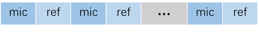
Dual Mic
Input audio data format: 16kHz, 16 bit, three channels (two are mic data, another is ref data). If AEC is not required, the input is two-channels of mic data.
The frame length of input audio data is fixed at 256 samples.
The input data is arranged as follows:

Three Mic
Input audio data format: 16kHz, 16 bit, four channels (three are mic data, another is ref data). If AEC is not required, the input is three-channels of mic data.
The frame length of input audio data is fixed at 256 samples.
The input data is arranged as follows:

If SSL module is enabled, the microphone positions corresponding to the mic data should be arranged counterclockwise. Refer SSL (Sound Source Localization).
Note
If AEC is not required, Set related parameters as follows: enable_aec = false, ref_num = 0.
Configurations
Definition of Configuration Parameters
AFE configuration includes microphone array, working mode, submodule switches, etc.
typedef struct afe_config{

    // AFE common parameter
    afe_mic_geometry_e  mic_array;          // microphone array. Make sure to choose the matched resource library
    int ref_num;                            // reference channel number, must be 0 or 1. AEC will be disabled if ref_num=0.
    int sample_rate;                        // sampling rate(Hz), must be 16000
    int frame_size;                         // frame length(samples), must be 256

    afe_mode_e afe_mode;                    // AFE mode, for ASR or voice communication.
    bool enable_aec;                        // AEC(Acoustic Echo Cancellation) module switch
    bool enable_ns;                         // NS(Noise Suppression) module switch
    bool enable_agc;                        // AGC(Automation Gain Control) module switch
    bool enable_ssl;                        // SSL(Sound Source Localization) module switch.

    // AEC module parameter
    afe_aec_mode_e aec_mode;                // AEC mode, signal process or NN method. NN method is not supported in current version.
    int aec_enable_threshold;               // ref signal amplitude threshold for AEC, the value should be in [0, 100].
                                            // larger value means the minimum echo to be cancelled will be larger.
    bool enable_res;                        // AEC residual echo suppression module switch
    afe_aec_filter_tap_e aec_cost;          // higher cost means longer filter length and more echo reduction
    afe_aec_res_aggressive_mode_e res_aggressive_mode;  // higher mode means more residual echo suppression but more distortion

    // NS module parameter
    afe_ns_mode_e ns_mode;                  // NS mode, signal process or NN method. NN method is only supports voice communication mode.
    afe_ns_cost_mode_e ns_cost_mode;        // low cost mode means 1channel NR and poorer noise reduction effect
    afe_ns_aggressive_mode_e ns_aggressive_mode;        // higher mode means more stationary noise suppression but more distortion

    // AGC module parameter
    int agc_fixed_gain;                     // AGC fixed gain(dB) applied on AFE output, the value should be in [0, 18].
    bool enable_adaptive_agc;               // adaptive AGC switch. Only supports voice communication mode.

    // SSL module parameter
    float ssl_resolution;                   // SSL solution(degree)
    int ssl_min_hz;                         // minimum frequency(Hz) of SSL module.
    int ssl_max_hz;                         // maximum frequency(Hz) of SSL module.
} afe_config_t;
If you need to change mic_array, both configuration and afe resource library should change accordingly. Refer to ${aivoice_lib_dir}/include/aivoice_afe_config.h for details.
Attention
Make sure the mic_array and ref_num in configuration match AFE input audio.
Preset Parameters
Preconfigured parameters for different microphone arrays and AFE modes are defined in ${aivoice_lib_dir}/include/aivoice_afe_config.h:
Microphone Array |
Speech Recognition Mode |
Voice Call Mode |
|---|---|---|
1mic |
AFE_CONFIG_ASR_DEFAULT_1MIC |
AFE_CONFIG_COM_DEFAULT_1MIC |
2mic30mm |
AFE_CONFIG_ASR_DEFAULT_2MIC30MM |
AFE_CONFIG_COM_DEFAULT_2MIC30MM |
2mic50mm |
AFE_CONFIG_ASR_DEFAULT_2MIC50MM |
AFE_CONFIG_COM_DEFAULT_2MIC50MM |
2mic70mm |
AFE_CONFIG_ASR_DEFAULT_2MIC70MM |
AFE_CONFIG_COM_DEFAULT_2MIC70MM |
3mic50mm |
AFE_CONFIG_ASR_DEFAULT_3MIC |
Not Supported |
Hardware Design Requirements
Microphone performance requirements
Omnidirectional MEMS microphone is recommended, it has better consistency.
Sensitivity: analog microphones ≥ -38dBV, digital microphones ≥ -26dBFS, ±1.5dB
Signal-to-noise ratio (SNR) : ≥ 60dB
Overall-harmonic-distortion (THD) : ≤ 1% (1kHz)
Acoustic overload point (AOP) : ≥ 120dB SPL
Speaker performance requirements
Harmonic distortion (THD) : under rated power 100Hz ~ 200Hz THD≤5%, 200Hz ~ 8kHz THD≤3%
Microphone Array Design Recommend
The distance between two microphones should be 3.0cm ~ 7.0 cm, preferably 5cm.
All microphone pickup holes are located in the same straight line, which is parallel to the horizontal plane.
The microphone orientation can be at any Angle between up and forward (towards the speaker).
Use the same microphone models from the same manufacturer for the array. It’s not recommended to use different microphone models in the same array.
It is recommended to use the same structural design for all the microphones in the same array to ensure consistency.
Receive Path Performance Requirements
Consistency
Frequency response consistency: free field spectrum (100Hz ~ 7kHz) response fluctuation < 3dB.
Phase consistency: phase difference between microphones (1kHz) < 10°.
Leakproofness
External speaker playback, the overall volume attenuation (100Hz ~ 8kHz) between blocked microphone pickup hole and unblocked microphone pickup hole > 15dB.
No Abnormality in the Spectrum
There should be no abnormal electrical noise.
There should be no data loss.
Spectrum Attenuation
There should be no significant attenuation below 7.5kHz.
Frequency Aliasing
Play the sweep signal (0Hz ~ 20kHz), and the recording signal has no significant frequency aliasing.
Echo Path Performance Requirements
Loopback mode for echo reference
Only supports hardware loopback for echo reference.
Echo reference signal position
It is recommended that the echo reference signal be as close to the speaker side as possible, and should be after EQ to avoid nonlinear caused by sound effects.
Reference signal gain
When the speaker playback at the maximum volume, the echo reference signal should not have clipping, the Recommended signal peak value is -3dB to -6dB.
Latency
Don’t have latency.
Total harmonic distortion
When the speaker playback at the maximum volume: 100Hz, THD≤10%; 200Hz ~ 500Hz, THD≤6%; 500Hz ~ 8kHz, THD≤3%.
Leakproofness
Device speaker playback, the overall volume attenuation (100Hz ~ 8kHz) between blocked microphone pickup hole and unblocked microphone pickup hole > 15dB.