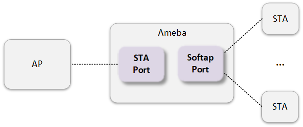
Wi-Fi Basic Architecture
WHC IPC is the default wireless communication architecture in the SDK, offering full-chip compatibility. Its core features include:
Dual-core Architecture
Based on the AP and NP dual-core design of the Ameba chip
Enables communication between Host and Device through internal IPC interfaces
No external Host controller required
Parallel Protocol Stack Execution
LWIP network protocol layer and Wi-Fi driver layer run on separate cores
Enables parallel processing to enhance data transmission efficiency
Modular Isolation Design
Achieves secure decoupling between the Wi-Fi driver layer and user application layer
Improves system security, reliability, and robustness

WHC IPC architecture
Wi-Fi Initialization
The SDK enables Wi-Fi functionality by default. In the main() function, it automatically calls wifi_init() to initialize Wi-Fi.
The complete Wi-Fi initialization flow is shown below:

Note
After successful Wi-Fi initialization, the device defaults to STA Mode.
To enable SoftAP Mode, call
wifi_start_ap()after Wi-Fi initialization is complete. Refer to Common SoftAP Workflows for details.
Wi-Fi Scan
This section introduces several common scan configurations. For advanced configurations, please refer to wifi_scan_networks().
Wi-Fi scanning modes include synchronous scanning and asynchronous scanning, with the complete workflow as follows:
Configuration:
Set
block=1when callingwifi_scan_networks()
Features:
Thread-safe: Only blocks the calling thread, allowing other threads to continue running
Recommended for: Most basic use cases

Synchronous scan flow
Configuration:
Set
block=0when callingwifi_scan_networks()Register a callback function using
scan_user_callback
Features:
Non-blocking: Returns immediately after validating parameters
Recommended for: Complex scenarios with high real-time requirements

Asynchronous scan flow
STA Mode
STA Connection Flow
This section introduces several common STA connection flows. For advanced configurations, refer to wifi_connect().
Configuration:
Set
block=1when callingwifi_connect()
Features:
Thread-safe: Only blocks the calling thread, allowing other threads to continue running
Recommended for: Most basic use cases

Synchronous Connection Flow
Configuration:
Set
block=0when callingwifi_connect()Register
RTW_EVENT_JOIN_STATUSfor event callback
Features:
Non-blocking: Returns immediately after validating parameters
Recommended for: Complex scenarios with high real-time requirements

Asynchronous Connection Flow
Note
Setting rtw_network_info::channel (e.g., obtained through a separate scan) can significantly reduce connection latency if the AP channel is known.
STA Auto-reconnect on Disconnection
The Wi-Fi auto-reconnection on disconnection mechanism is designed to establish or restore a network connection seamlessly or with minimal user intervention.
Disconnections are divided into two situations, at which point it will automatically initiate a reconnection.
The connection initiated by STA failed.
The STA is passively disconnected due to the AP.
Item |
Phenomenon |
Common Causes |
|---|---|---|
Connection Failure |
Authentication/Association Timeout |
|
4-way Handshake Failure |
||
DHCP Timeout |
||
Passive Disconnection |
Beacon Frame Loss |
|

Auto-reconnect Flow
Once a disconnection event is detected, the system follows an intelligent strategy to balance recovery speed with resource consumption, initiating a reconnection process without manual user intervention. To prevent battery drain in environments with persistently poor signal or to avoid placing an unnecessary burden on the network, there is a configurable waiting interval between reconnection attempts, as well as a maximum number of retries.
Parameter |
Type |
Value |
Description |
Default |
|---|---|---|---|---|
auto_reconnect_en |
u8 |
0 / 1 |
Disable / Enable auto-reconnection mechanism. |
1 |
auto_reconnect_count |
u8 |
>= 1 |
Configure the maximum number of auto-reconnection attempt. Note 0xFF indicates unlimited attempts. |
10 |
auto_reconnect_interval |
u8 |
— |
The interval between each reconnection attempt, in seconds. |
5 |
Note
After configuring the following settings, you can implement the custom reconnection function by referring to the file example_wifi_user_reconnect.c.
wifi_user_config.auto_reconnect_en = 0;
STA Auto-reconnect on Power-up
The Wi-Fi auto-reconnection on power-up mechanism is designed to allow a client to automatically recognize saved Wi-Fi profiles after a reboot. Using this information, it then connects to the target network, ensuring a persistent and reliable connection to known networks without any manual intervention.
After each successful connection to a Wi-Fi network, the Ameba chip saves a profile information such as security credentials (password/security type), channel, and the Service Set Identifier (SSID). This profile is stored in the device’s non-volatile storage (flash). Following an unexpected power cycle or a manual reboot, the device automatically reads this profile and begins the autonomous connection process: scanning the environment and associating with the target network, without waiting for user commands or application requests.

Auto-reconnect on Power-up Flow
The feature is enabled by default. It can be disabled by setting wifi_user_config.fast_reconnect_en = 0. When disabled, the device need to trigger the network connection process through a command or software scheduling after each reboot.
SoftAP Mode
Common SoftAP Workflows
The common SoftAP workflow is shown in the following figure:

SoftAP MAC Address
The SoftAP MAC address is derived by offsetting the STA MAC address (chip’s base MAC address) by default.
This offset is controlled via wifi_user_config.softap_addr_offset_idx:
Chip MAC Address |
softap_addr_offset_idx |
SoftAP MAC Address |
|---|---|---|
00:e0:4c:01:02:03 |
0 |
02:e0:4c:01:02:03 |
1 (SDK Default) |
00:e1:4c:01:02:03 |
|
5 |
00:e0:4c:01:02:04 |
To set the SoftAP MAC address to the chip’s base MAC address, configure:
wifi_user_config.concurrent_enabled = 0;
Note
When wifi_user_config.concurrent_enabled = 0, STA and SoftAP cannot operate simultaneously. For details, see SoftAP and STA Concurrent.
Channel Switch Announcement (CSA) for SoftAP
SoftAP can perform channel switching and notify all connected STAs by calling wifi_ap_switch_chl_and_inform(). This enables STAs to quickly and seamlessly follow SoftAP to the new channel, preventing connection interruptions.
The channel switching sequence diagram for SoftAP is illustrated below:

The CSA Information Element (CSA IE) format in Beacon and CSA Action frames is as follows. Specific field values are determined by the input parameters of wifi_ap_switch_chl_and_inform():
Field |
Length |
Meaning |
Source |
|---|---|---|---|
Element ID |
1 byte |
CSA IE ID |
Fixed |
Channel Switch Mode |
1 byte |
STA transmission restriction mode |
|
New Channel Number |
1 byte |
New channel for SoftAP |
|
Channel Switch Count |
1 byte |
Remaining Beacon intervals to switch |
Set from |
Note
Refer to
rtw_csa_parmfor detailed descriptions when configuring parameters forwifi_ap_switch_chl_and_inform().Regardless of the CSA Action frame type (
rtw_csa_parm::action_type) selected, Beacon frames always include the CSA IE prior to channel switching.
Example: SoftAP switches to channel 7 after 10 Beacon intervals, sending 2 broadcast CSA Action frames per interval, without restricting STA transmission:
struct rtw_csa_parm csa_param = {0};

csa_param.new_chl = 7;
csa_param.chl_switch_cnt = 10;
csa_param.bc_action_cnt = 2;
csa_param.action_type = 1;
csa_param.chl_switch_mode = 0;
csa_param.callback = NULL;

wifi_ap_switch_chl_and_inform(&csa_param);
Note
In SoftAP/STA concurrent mode, if the STA is already connected to an AP, SoftAP channel switching will cause the STA to disconnect.
SoftAP and STA Concurrent
Ameba supports simultaneous operation of STA mode and SoftAP mode:
This feature is enabled by default in the SDK:
wifi_user_config.concurrent_enabled = 1;
Wi-Fi operates in SoftAP/STA concurrent mode when the following conditions are met simultaneously:
The SoftAP interface is started.
The STA interface is connected or in the connection process.
Key differences compared to only STA or SoftAP mode development include:
Two MAC addresses must be reserved. The STA interface’s MAC address is derived from efuse, while the SoftAP MAC address is generated by offsetting the STA MAC address. For details, refer to SoftAP Configuration.
When the STA interface connects, SoftAP automatically switches to the same channel as the STA interface. (The CSA mechanism can minimize STA disconnections under SoftAP; see Channel Switch Announcement (CSA) for SoftAP for details.)
Disable SoftAP/STA concurrent functionality with the following setting:
wifi_user_config.concurrent_enabled = 0;
After disabling concurrent, these restrictions apply:
After SoftAP starts, the STA interface cannot connect.
When the STA interface is connected or connecting, SoftAP cannot be enabled.
Typically disabled only when binding SoftAP MAC to chip MAC address.
SoftAP Configuration
This section provides parameters to configure the capabilities, behavior, and other aspects of the SoftAP mode.
Wi-Fi Config file: component/soc/usrcfg/amebaxxx/ameba_wificfg.c
Parameter |
Type |
Value |
Description |
Default |
|---|---|---|---|---|
ap_sta_num |
u8 |
1 ~ 5 |
Maximum number of allowed connected devices for SoftAP. |
5 |
ap_polling_sta |
u8 |
0 / 1 |
SoftAP periodically sends polling frames to check STA online status (not currently supported) |
0 |
softap_addr_offset_idx |
u8 |
0 ~ 5 |
Specifies the incremental offset index (increment by 1) for SoftAP MAC address. See SoftAP MAC Address |
1 |
Parameter |
Type |
Value |
Description |
Default |
|---|---|---|---|---|
ap_sta_num |
u8 |
1 ~ 12 |
Maximum number of allowed connected devices for SoftAP. |
12 |
ap_polling_sta |
u8 |
0 / 1 |
SoftAP periodically sends polling frames to check STA online status (not currently supported) |
0 |
softap_addr_offset_idx |
u8 |
0 ~ 5 |
Specifies the incremental offset index (increment by 1) for SoftAP MAC address. See SoftAP MAC Address |
1 |
Promiscuous Mode
Promiscuous mode can deliver raw Wi-Fi packets directly to the application layer.
API
Call wifi_promisc_enable() to configure and enable promiscuous mode.
Common Workflow
The typical workflow for promiscuous mode is shown below:
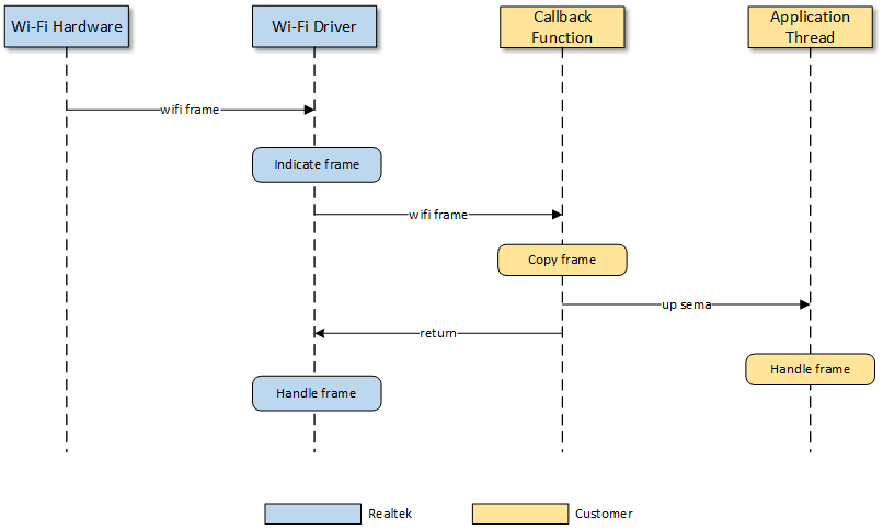
Note
The callback function will block the execution of the Wi-Fi driver. Therefore, only simple and fast operations should be performed within it. For complex processing, it is recommended to create a separate task.
Application Example
Wi-Fi Antenna Diversity
Antenna Diversity (ANTDIV) enhances the performance and reliability of wireless communications by leveraging multiple antennas. The technique works by dynamically selecting the antenna with the best signal quality for data traffic. This is primarily done to combat multipath fading, a form of signal degradation that occurs when radio waves travel multiple paths, causing destructive interference at the receiver. By choosing the strongest and cleanest signal path, ANTDIV ensures higher signal quality and more reliable connectivity.
Working Mechanism
The ANTDIV feature of the Ameba chip is implemented in two parts:

Hardware: The hardware’s behavior is distinguished by different operating modes,
Data Reception (RX): For each incoming packet, the hardware utilizes its preamble phase to rapidly switch between and evaluate the antennas. This process identifies the antenna with the best signal quality. Subsequently, the hardware locks onto this optimal antenna to receive the remainder of the packet’s payload.
Link Idle (RX-idle): The hardware uses a fixed antenna to perform environmental listening and Clear Channel Assessment (CCA). This antenna is the one determined as optimal by the software in the preceding cycle.
Data Transmission (TX): The hardware uses a fixed antenna, selected by the software in the preceding cycle, for data transmission.
Software: The software periodically collects statistics on the signal strength metrics of received signals on each antenna. Based on this data, it determines the “optimal” antenna. This selected antenna is then used for the RX-idle and TX stages in the subsequent cycle.
The ANTDIV mechanism supported by the Ameba chip achieves dynamic optimization through the following steps:
Periodic Monitoring: The system periodically triggers an “antenna training” phase. During this phase, the system rapidly alternates between the main (Main) and auxiliary (Aux) antennas to collect signal samples from each.

Performance Evaluation: The system evaluates target metrics of the data packets received during the training phase.
Received Signal Strength Indication (RSSI): Measures the power level of the received signal. Generally, a stronger signal is better.
Error Vector Magnitude (EVM): Measures the degree of signal distortion or quality. A lower EVM value indicates higher signal quality.
Throughput (TP): Measures the actual effective data transfer rate.
Decision Logic: The system employs a predefined algorithm to evaluate the performance metrics collected from each antenna during the training period. Based on this analysis, it selects the antenna that exhibited the optimal overall performance to handle the ongoing data traffic.

The ANTDIV mechanism supported by the Ameba chip achieves dynamic optimization through the following steps:
Periodic Monitoring: The system periodically triggers an “antenna training” phase. During this phase, the system rapidly alternates between the main (Main) and auxiliary (Aux) antennas to collect signal samples from each.
Performance Evaluation: The system evaluates target metrics of the data packets received during the training phase.
Received Signal Strength Indication (RSSI): Measures the power level of the received signal. Generally, a stronger signal is better.
Error Vector Magnitude (EVM): Measures the degree of signal distortion or quality. A lower EVM value indicates higher signal quality.
Throughput (TP): Measures the actual effective data transfer rate.
Decision Logic: The system employs a predefined algorithm to evaluate the performance metrics collected from each antenna during the training period. Based on this analysis, it selects the antenna that exhibited the optimal overall performance to handle the ongoing data traffic.
Switching Control
The functional support and control pins may vary for different Radio Front-End (RFE) types. For specific details, please refer to the document WR-date-IC-RFE Type Definition-Rxx.xlsx, which can be obtained from your HW FAE.
After the chip tape-out, the RFE type and its corresponding control pin mapping are hardwired. The RFE type identifier is programmed into the eFuse at address 0x13A. Developers must read this value to ensure the software configuration matches the pin mapping defined in the chip’s hardware.
Different RFE types typically use different control pins; for instance, the diagram shows RFE Type 2 using PB2/PB3 to control an SPDT (Single Pole Double Throw) switch to select the antenna.

Note
Not all RFE types support the ANTDIV mechanism; actual support depends on the chip’s hardware design.
The functional support and control pins may vary for different Radio Front-End (RFE) types. For specific details, please refer to the document WR-date-IC-RFE Type Definition-Rxx.xlsx, which can be obtained from your HW FAE.
After the chip tape-out, the RFE type and its corresponding control pin mapping are hardwired. The RFE type identifier is programmed into the eFuse at address 0x13A. Developers must read this value to ensure the software configuration matches the pin mapping defined in the chip’s hardware.
As illustrated in the figure below, different RFE types generally correspond to different control pins (e.g., the left diagram shows PA4/PA5 controlling a DPDT switch for antenna selection, while the right diagram shows PA15/PA16 controlling an SPDT switch).
Note
Not all RFE types support the ANTDIV mechanism; actual support depends on the chip’s hardware design.
ANTDIV User Guide
Software Configuration
Ameba Wi-Fi provides parameters for selecting different ANTDIV modes.
Parameter |
antdiv_mode |
|
|---|---|---|
Type |
u8 |
|
Value |
RTW_ANTDIV_AUTO |
Automatic antenna switching mode |
RTW_ANTDIV_FIX_MAIN |
Fixed to MAIN antenna |
|
RTW_ANTDIV_FIX_AUX |
Fixed to AUX antenna |
|
RTW_ANTDIV_DISABLE |
Disable antenna diversity mechanism |
|
Default |
RTW_ANTDIV_DISABLE |
|
Note
If the antenna diversity mechanism is required, wifi_user_config.antdiv_mode must not be set to RTW_ANTDIV_DISABLE.
Firmware Compilation
Navigate to
{SDK}/amebaxxx_gcc_projectand run the following command:./menuconfig.py
Locate , select , then save and exit.
----Connectivity config----
    CONFIG WHC INTF --->
    CONFIG WIFI --->
             SDK MODE (NORMAL INIC)  --->
      [ ]    Enable WPS
      [ ]    Enable CSI
      [*]    Enable ANTDIV
      ---
    CONFIG BT --->
    ... --->
Navigate to
{SDK}/amebaxxx_gcc_projectagain and run the following command:./build.py
Debug Commands
Execute AT+WLDBG=antdiv_get to retrieve the antenna currently selected for the TRX。
#AT+WLDBG=antdiv_get              //Wi-Fi IPS
[WLDBG]: _AT_WLAN_IWPRIV_
[WLAN-A] [iwpriv_command] cmd name: antdiv_set
[WLAN-A] get antdiv m:1+P:02017560(ips:BITx->PA_x)  //mode-RTW_ANTDIV_FIX_MAIN; P(PIN)-check rfe control PIN level

#AT+WLDBG=antdiv_get              //Wi-Fi LPS
[WLDBG]: _AT_WLAN_IWPRIV_
[WLAN-A] [iwpriv_command] cmd name: regu
[WLAN-A] get antdiv m:1+ant:0     //m(mode)-RTW_ANTDIV_FIX_MAIN; ant(antenna):0-MAIN_ANT/1-AUX_ANT
Execute AT+WLDBG=antdiv_set,value to modify the currently configured ANTDIV mode.。
#AT+WLDBG=antdiv_set,0
[WLDBG]: _AT_WLAN_IWPRIV_
[WLAN-A] [iwpriv_command] cmd name: antdiv_set
[WLAN-A] change antdiv=0[0-auto;1-main;2-aux;f-disable]