Overview
The Universal Serial Bus On-The-Go (USB OTG) is originally supported by Linux USB subsystem with Realtek’s dedicatedly designed USB PHY driver and a few changes at DWC2 USB controller driver.
Architecture
The USB software architecture is illustrated in the following figure.

Implementation
The original USB is supported by Linux USB subsystem.
File |
Description |
|---|---|
<linux>/drivers/usb/dwc2/ |
DWC2 host & device controller driver, with changes by Realtek |
<linux>/drivers/usb/core/ |
HCD core |
<linux>/drivers/usb/gadget/ |
Gadget core |
<linux>/drivers/usb/gadget/function/ |
Device classes, such as ADB, CDC ACM, HID, MSC, etc. |
<linux>/drivers/usb/class/cdc-acm.* |
CDC ACM host class |
<linux>/drivers/usb/storage/* |
MSC host class |
For more details of USB subsystem, refer to usb system v5.4 or usb system v6.6.
Realtek USB PHY driver is implemented as following files:
File |
Description |
|---|---|
<linux>/drivers/rtkdrivers/usb_phy/Kconfig |
USB PHY driver Kconfig |
<linux>/drivers/rtkdrivers/usb_phy/Makefile |
USB PHY driver Makefile |
<linux>/drivers/rtkdrivers/usb_phy/phy-rtk-usb.c |
USB PHY functions |
<linux>/drivers/rtkdrivers/usb_phy/phy-rtk-usb.h |
USB PHY API declaration |
Configuration
DTS Configuration
USB PHY DTS Configuration
USB PHY DTS node is defined in <dts>/rtl8730e-ocp.dtsi:
usb_phy: usb-phy@41000000 {
   compatible = "realtek,otg-phy";
   reg = <0x400B0000 0x20>,
   <0x41000060 4>,
   <0x42000100 0x10>,
   <0x4200825C 4>;
   #phy-cells = <0>;
   clocks = <&rcc RTK_CKE_USB>;
   rtk,cal-data = <0x00 0xE0 0x9D>,
      <0x00 0xE1 0x19>,
      <0x00 0xE2 0xDB>,
      <0x00 0xE4 0x68>,
      <0x01 0xE5 0x0A>,
      <0x01 0xE6 0xD8>,
      <0x02 0xE7 0x52>,
      <0x01 0xE0 0x04>,
      <0x01 0xE0 0x00>,
      <0x01 0xE0 0x04>;
   rtk,usb-phandle = <&usb>;
   rtk,usb-force-role-en = <1>;
   status = "okay";
};
The DTS configurations of USB PHY are listed below:
Property |
Description |
Configurable? |
|---|---|---|
compatible |
ID to match the Realtek USB PHY driver with the USB PHY device |
No |
reg |
USB PHY register resource |
No |
#phy-cells |
Indicates how many cells are needed to specifically describe a USB PHY, fixed at 0 for only one USB phy |
No |
clocks |
The clock source of USB PHY |
No |
rtk,cal-data |
The calibration data of USB PHY |
No |
rtk,usb-phandle |
The USB Pointer Handle of USB PHY |
No |
rtk,usb-force-role-en |
Enables forced switching between USB Host and Device modes. |
1/0 |
status |
USB PHY status |
disabled/okay |
USB PHY node is enabled by default. To disable it, overwrite the node status to disabled by node reference in higher level DTS file, such as chip specific DTS file or board specific DTS file:
&usb_phy{
   status = "disabled";
};
USB DTS Configuration
USB DTS node is defined in <dts>/rtl8730e-ocp.dtsi:
usb: usb@40080000 {
   compatible = "realtek,dwc-otg";
   reg = <0x40080000 0x20000>;
   interrupts = <GIC_SPI 39 IRQ_TYPE_LEVEL_HIGH>;
   g-rx-fifo-size = <512>;
   g-np-tx-fifo-size = <256>;
   g-tx-fifo-size = <128 120>;
   status = "okay";
   endpoints {
      ep1in {
         ep_name = "ep1in";
         ep_type = <0x0E>; // USB_EP_CAPS_TYPE_ALL
      };
      ep2out {
         ep_name = "ep2out";
         ep_type = <0x0E>; // USB_EP_CAPS_TYPE_ALL
      };
      ep3in {
         ep_name = "ep3in";
         ep_type = <0x0E>; // USB_EP_CAPS_TYPE_ALL
      };
      ep4out {
         ep_name = "ep4out";
         ep_type = <0x0E>; // USB_EP_CAPS_TYPE_ALL
      };
      ep5in {
         ep_name = "ep5in";
         ep_type = <0x0E>; // USB_EP_CAPS_TYPE_ALL
      };
      ep5out {
         ep_name = "ep5out";
         ep_type = <0x0E>; // USB_EP_CAPS_TYPE_ALL
      };
   };
};
The DTS configurations of USB are listed below:
Property |
Description |
Configurable? |
|---|---|---|
compatible |
ID to match the DWC2 controller driver with the USB OTG device |
No |
reg |
USB register resource |
No |
interrupts |
The GIC interrupt for USB |
No |
g-rx-fifo-size |
The periodic Rx FIFO size for the USB device (unit: DWORDS). |
16~512 |
g-np-tx-fifo-size |
The non-periodic Tx FIFO size for the USB device (unit: DWORDS). |
16~256 |
g-tx-fifo-size |
An array of TX FIFO sizes in dedicated FIFO mode. Each value corresponds to one EP starting (unit: DWORDS). Realtek USB works in shared FIFO mode, therefore this configuration will be ignored. |
16~256 |
status |
USB device status |
disabled/okay |
endpoints |
Allows USB Endpoint address configuration to meet specific client requirements. |
Yes |
Note
The total Data FIFO depth is 1016, that means the result of \(g-rx-fifo-size + g-np-tx-fifo-size + g-tx-fifo-size\) should not be larger than 1016.
DO NOT change the default configurations unless indeed necessary.
The USB node is enabled by default. To disable it, overwrite the node status to disabled by node reference in higher level DTS file, such as chip specific DTS file or board specific DTS file:
&usb{
   status = "disabled";
};
Build Configuration
The USB functions can be configured as built-in functions in kernel image or independent kernel modules.
Build-in Configuration
To build USB functions into kernel image:
Select
Yfor .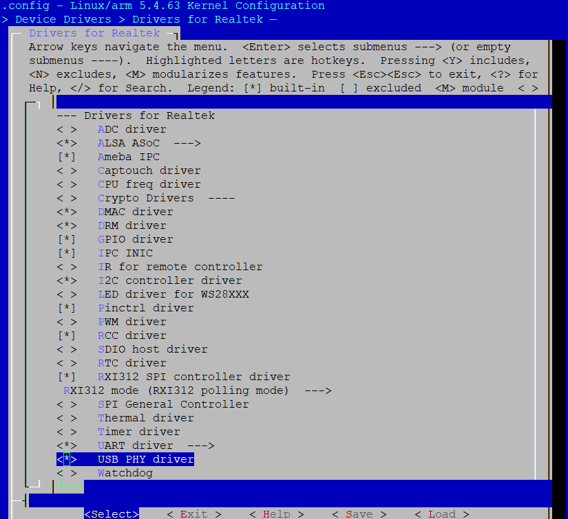
Select
Yfor .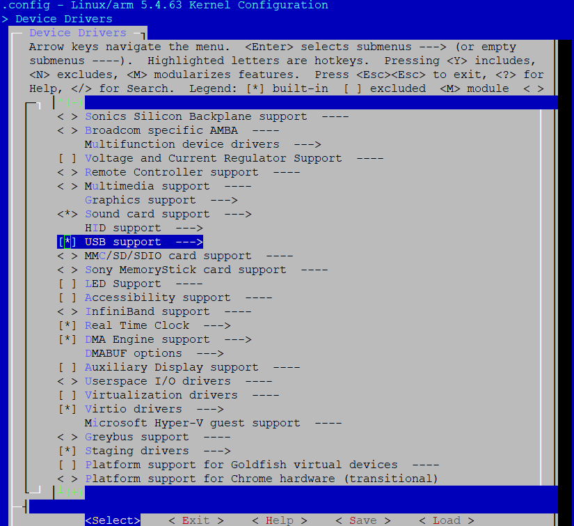
Select required USB mode.
For host mode, select
Yfor .For device mode, select
Yfor .For OTG mode, select
Yfor both and .
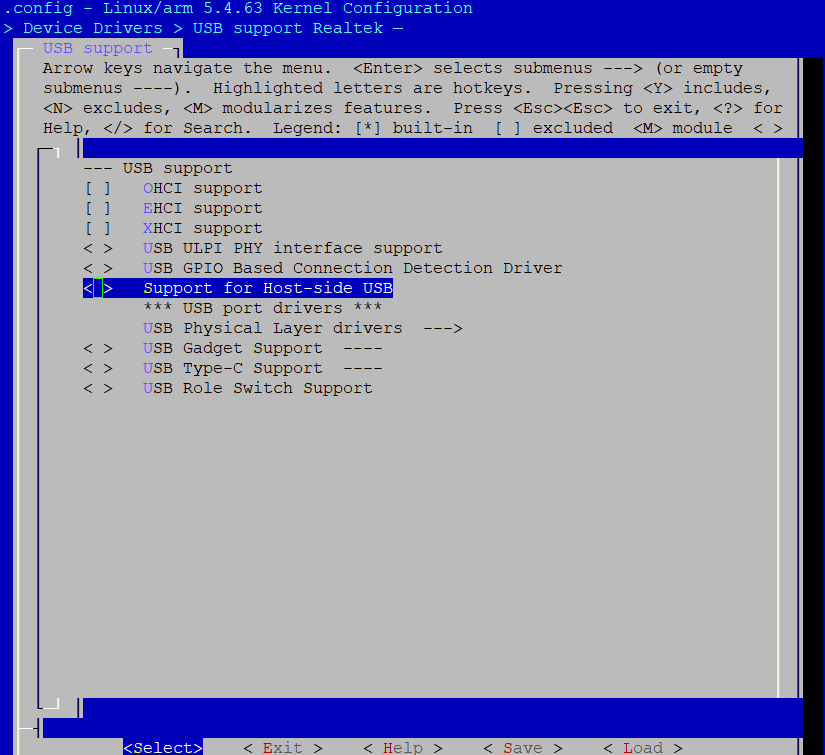
Select
Yfor .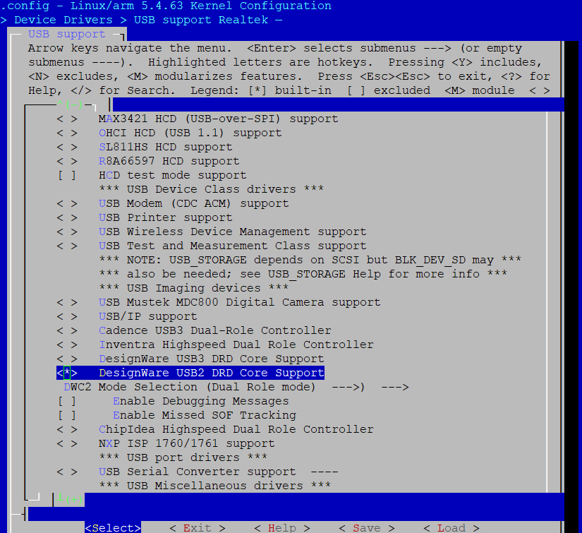
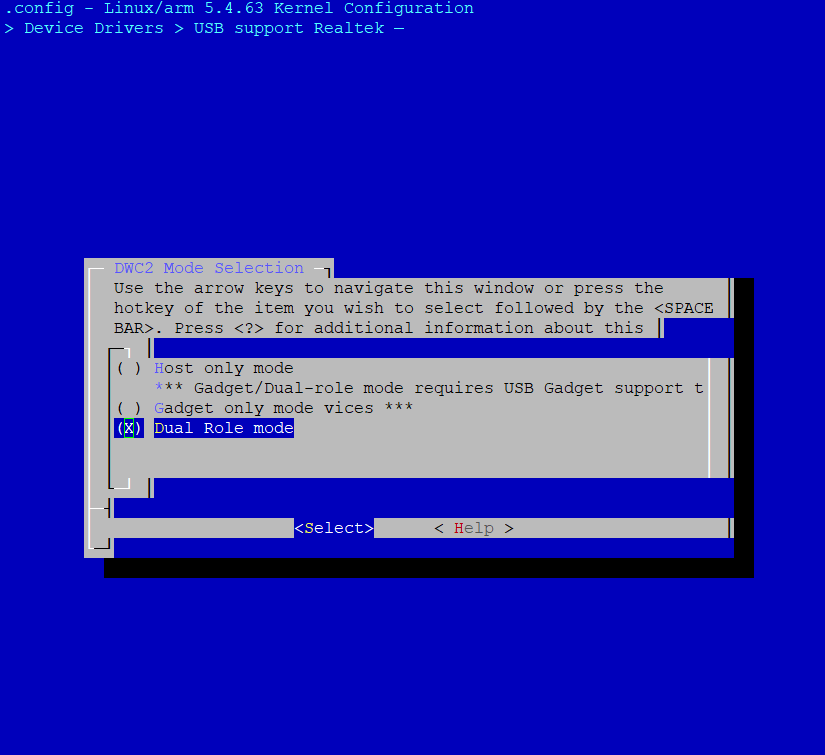
Check DWC2 mode selection.
For USB host, select
Yfor Host only modeFor USB device, select
Yfor Gadget only modeFor USB OTG mode, select
Yfor Dual Role mode.
Select configurations for required class, refer to the following sections for details.
Module Configuration
To build USB functions as kernel modules:
Select
Mfor .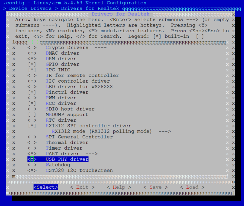
Select
Yfor .
Select required USB mode.
For host mode, select
Mfor .For device mode, select
Mfor .For OTG mode, select
Mfor both and .
Select
Mfor .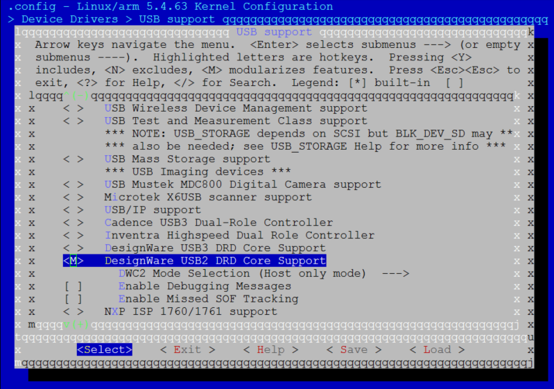
Check DWC2 mode selection.
For USB host, select
Yfor Host only modeFor USB device, select
Yfor Gadget only modeFor USB OTG mode, select
Yfor Dual Role mode.
Select configurations for required class, refer to the following sections for details.
Load kernel modules at runtime
Where the
<kernel_ver>below depends on the kernel version, such as 5.4.63.For host mode, type the following command sequences to load USB common host drivers before loading any USB class specific modules:
insmod /lib/modules/<kernel_ver>/kernel/drivers/rtkdrivers/usb_phy/phy-rtk-usb.ko
insmod /lib/modules/<kernel_ver>/kernel/drivers/usb/common/usb-common.ko
insmod /lib/modules/<kernel_ver>/kernel/drivers/usb/core/usbcore.ko
insmod /lib/modules/<kernel_ver>/kernel/drivers/usb/dwc2/dwc2.ko
For device mode, type the following command sequences to load USB common device drivers before loading any USB class specific modules:
insmod /lib/modules/<kernel_ver>/kernel/drivers/rtkdrivers/usb_phy/phy-rtk-usb.ko
insmod /lib/modules/<kernel_ver>/kernel/drivers/usb/common/usb-common.ko
insmod /lib/modules/<kernel_ver>/kernel/drivers/usb/gadget/udc/udc-core.ko
insmod /lib/modules/<kernel_ver>/kernel/drivers/usb/gadget/libcomposite.ko
insmod /lib/modules/<kernel_ver>/kernel/drivers/usb/dwc2/dwc2.ko
Host Solution
In USB host mode, USB OTG can enumerate the attached USB device and initiate the USB transfer.
Only the usage of several host classes are described in this section, for more information, refer to usb v5.4 or usb v6.6.
Transparent Communication Host Solution
Configuration
Besides the common USB host configurations, extra configurations are required to support USB CDC ACM class driver, and user can choose to configure it as built-in functions or independent kernel modules.
The following configurations provide an example to support a typical CDC ACM device: USB serial port.
Adjust the configurations as required.
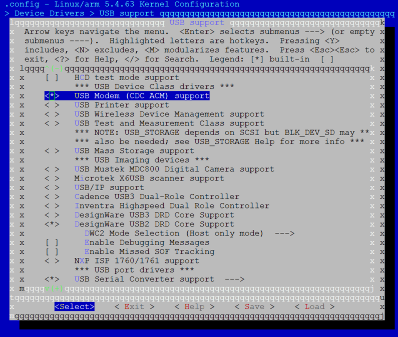
Built-in Configuration
Enter USB support menu, type Y to select USB Modem (CDC ACM) support and USB Serial Converter support options:
Module Configuration
Enter USB support menu, type
Mto select USB Modem (CDC ACM) support and USB Serial Converter support options: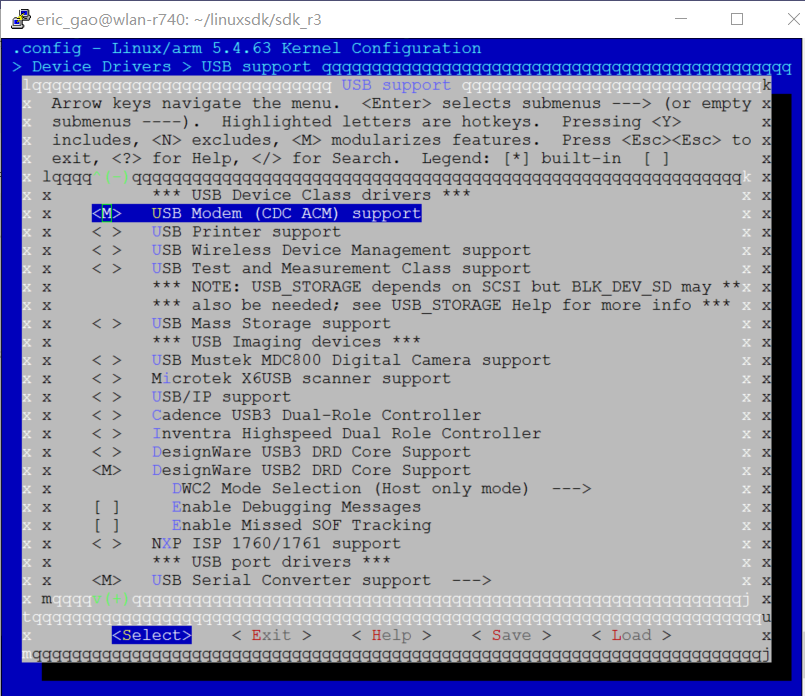
Load kernel modules for CDC ACM class after loading common USB host modules.
insmod /lib/modules/<kernel_ver>/kernel/drivers/usb/class/cdc-acm.ko
insmod /lib/modules/<kernel_ver>/kernel/drivers/usb/serial/usbserial.ko
APIs for Application
Refer to usb guide x332.
Usage Example
Once configured as a CDC ACM host, the SoC will recognize the attached CDC ACM device as a TTY device, and will be able to communicate with the CDC ACM device through TTY interface.
Connect a CDC ACM device to SoC with USB cable, the following log will be printed on the console:
dwc2 40080000.usb: Set speed to high-speed
usb 1-1: new high-speed USB device number 2 using dwc2
dwc2 40080000.usb: Set speed to high-speed
cdc_acm 1-1:1.0: ttyACM0: USB ACM device
Communicate with the CDC ACM device through device node
/dev/ttyACM0, for example:Send data to CDC ACM device:
echo helloworld > /dev/ttyACM0Receive data from CDC ACM device:
cat /dev/ttyACM0
Refer to <sdk>/tests/usbh_cdc_acm for CDC ACM host demo.
Mass Storage Host Solution
Configuration
Besides the common USB host configurations, extra configurations are required to support USB mass storage class driver, and user can choose to configure it as built-in functions or independent kernel modules.
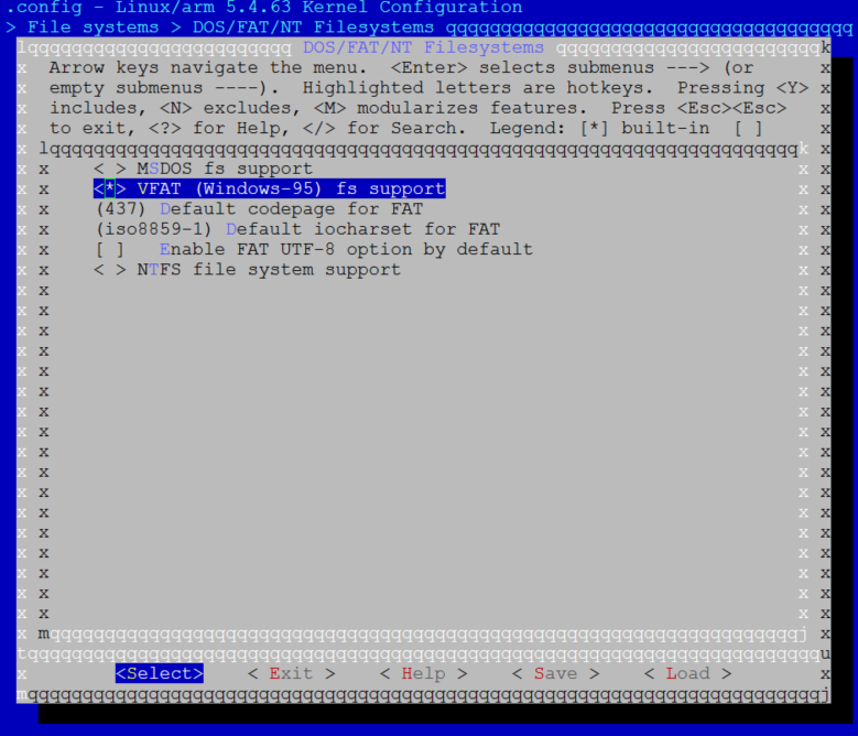
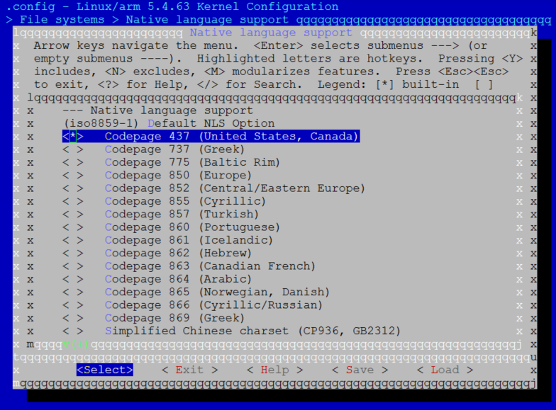
The following configurations provide an example to support a typical mass storage device: UDISK with Realtek card reader solution and formatted with FAT32 file system.
Common configurations required by USB mass storage class driver:
and :
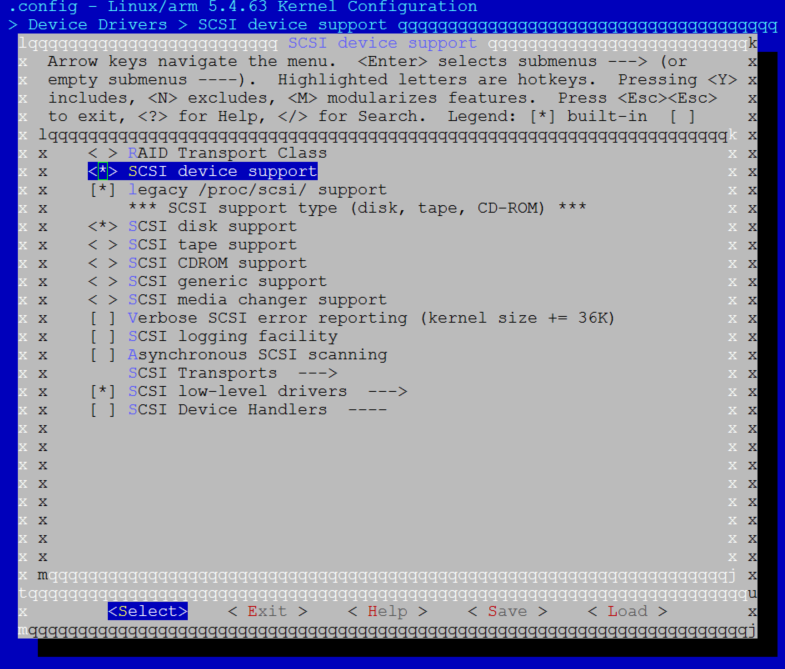
:
and :
Adjust the configurations as required.
Built-in Configuration
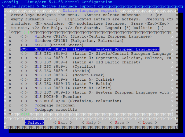
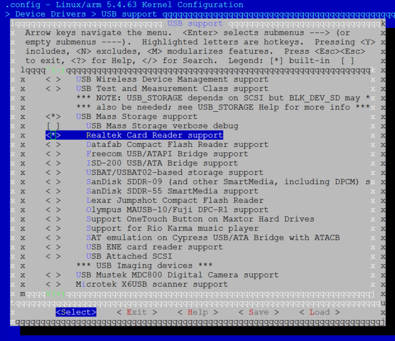
Enter USB support menu, type Y to select USB Mass Storage support and Realtek Card Reader support options:
Module Configuration
Enter USB support menu, type
Mto select USB Mass Storage support and then Realtek Card Reader support options:
Load kernel modules for mass storage class after loading common USB host modules.
insmod /lib/modules/<kernel_ver>/kernel/drivers/usb/storage/usb-storage.ko
insmod /lib/modules/<kernel_ver>/kernel/drivers/usb/storage/ums-realtek.ko
APIs for Application
Refer to usb guide x498.
Usage Example
Here is the example to test the USB host mass storage driver with supported UDISK.
Connect an UDISK to SoC, the following log will be printed on console.
usb 1-1: USB disconnect, device number 2
dwc2 40080000.usb: Set speed to high-speed
usb 1-1: new high-speed USB device number 3 using dwc2
dwc2 40080000.usb: Set speed to high-speed
usb-storage 1-1:1.0: USB Mass Storage device detected
scsi host0: usb-storage 1-1:1.0
scsi 0:0:0:0: Direct-Access TOSHIBA USB FLASH DRIVE PMAP PQ: 0 ANSI: 6
sd 0:0:0:0: [sda] 30253056 512-byte logical blocks: (15.5 GB/14.4 GiB)
sd 0:0:0:0: [sda] Write Protect is off
sd 0:0:0:0: [sda] Write cache: disabled, read cache: enabled, doesn't support DPO or FUA
sda: sda1
sd 0:0:0:0: [sda] Attached SCSI removable disk
Mount UDISK device.
mkdir /mnt/udisk
mount -t vfat /dev/sda1 /mnt/udisk
Access UDISK device. Create a file and write/read it.
cd /mnt/udisk
echo hello >> test.txt
cat test.txt
hello
Unmount UDISK device
umount /mnt/udiskDisconnect the UDISK device
usb 1-1: USB disconnect, device number 2
Video Host Solution
Configuration
Besides the common USB host configurations, extra configurations are required to support USB UVC class driver, and user can choose to configure it as built-in functions or independent kernel modules.
The following configurations provide an example to support a typical UVC device: UVC camera.
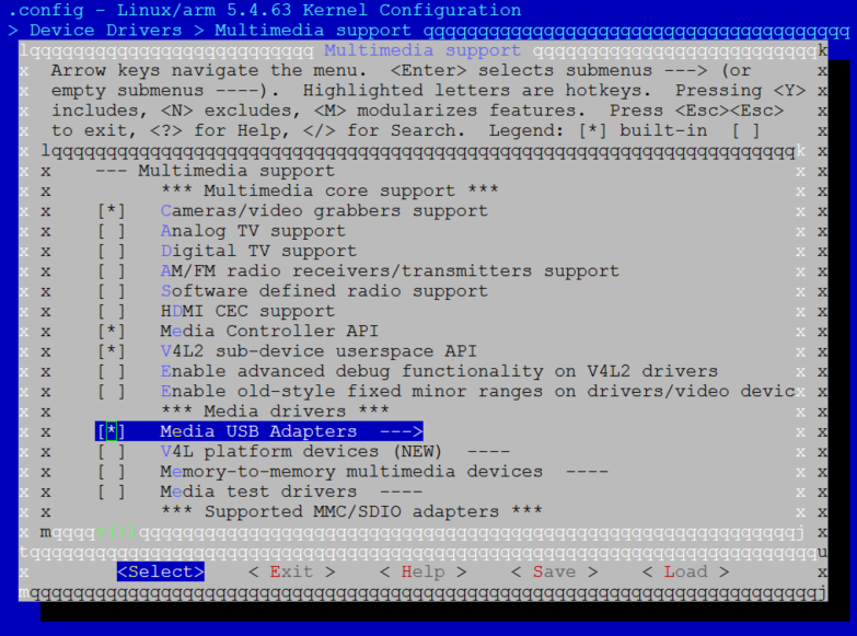
Common configurations required by UVC camera, selected as default in SDK:
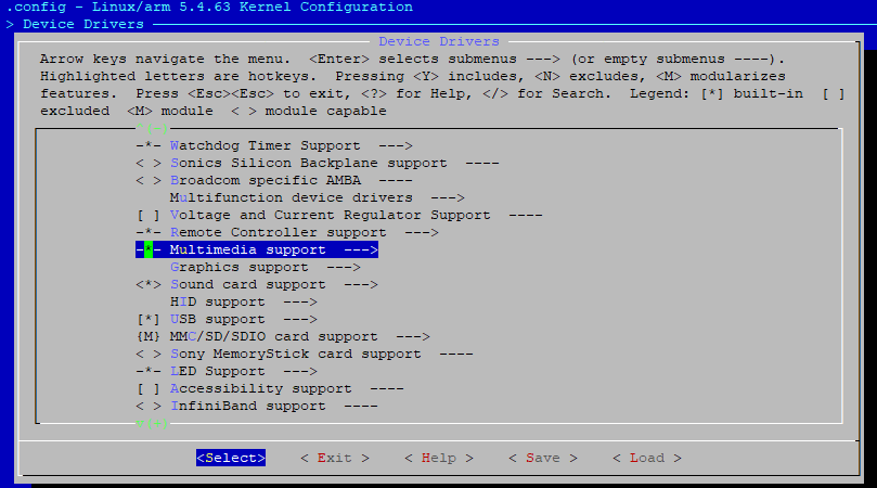
:
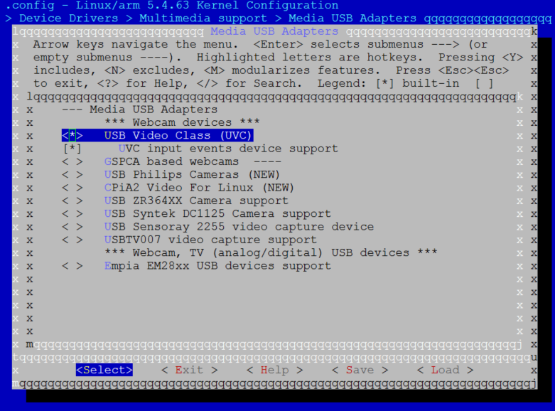
Built-in Configuration
Enter Media USB Adapters and type Y to select USB Video Class (UVC):
Module Configuration
Enter Media USB Adapters and type
Mto select USB Video Class (UVC) :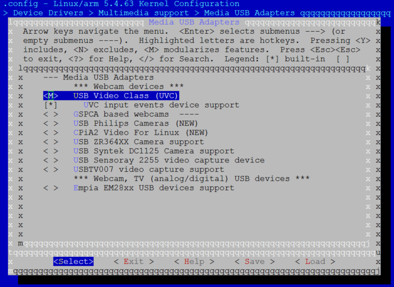
Load kernel modules about UVC class after loading common USB host modules.
insmod /lib/modules/<kernel_ver>/kernel/drivers/media/usb/uvc/uvcvideo.ko
APIs for Application
It treats UVC device as a V4L2 device. Refer to linux video to get more information about V4L2 API.
Usage Example
The following is a usage simple for a typical UVC device: USB camera.
Once the USB camera is plugged into USB cable, the following log will print on console.
dwc2 40080000.usb: Set speed to high-speed
usb 1-1: new high-speed USB device number 2 using dwc2
dwc2 40080000.usb: Set speed to high-speed
uvcvideo: Found UVC 1.00 device USB Camera (0bda:5842)
input: USB Camera: USB Camera as /devices/platform/ocp/40080000.usb/usb1/1-1/1-1:1.0/input/input1
User can use IOCTL with V4L2 library API to access USB camera.
Find the UVC demo at <sdk>/tests/usbh_uvc, which is an example that capture image from UVC camera and save it to a SD card.
Note
SD card shall be mounted before running the UVC demo.
Vendor-Specific Host Solution
Vendor class is designed for user to develop customized USB host class.
Configuration
Besides the common USB host configurations, extra configurations are required to support USB vendor class driver, and user can choose to configure it as built-in functions or independent kernel modules.
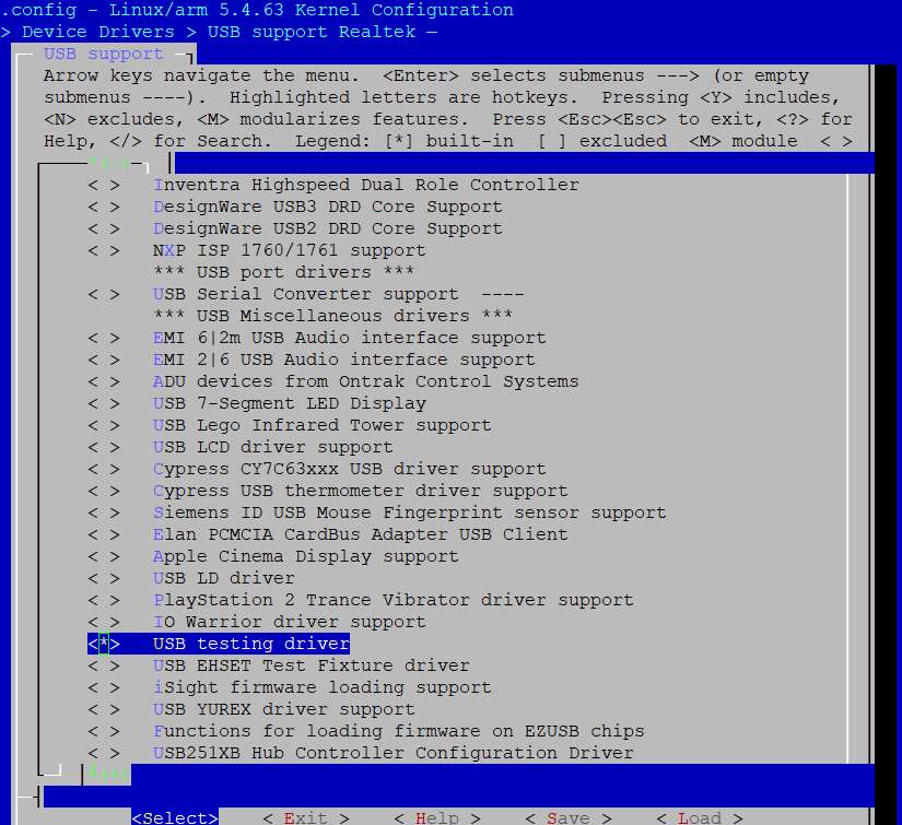
Built-in Configuration
Type Y to select USB testing driver:
Module Configuration
Type
Mto select USB testing driver: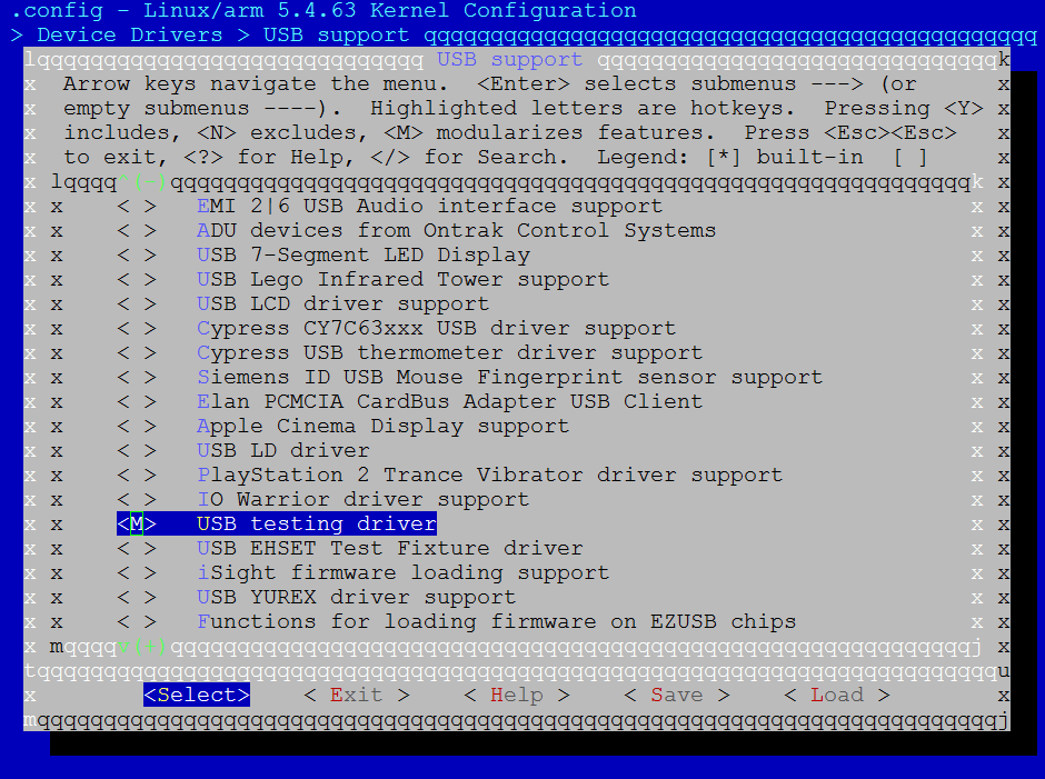
Load kernel modules about vendor class after loading common USB host modules.
insmod /lib/modules/<kernel_ver>/kernel/drivers/usb/misc/usbtest.ko
APIs for Application
None.
Usage Example
Find the USB host vendor demo for user space at <sdk>/tests/usbh_vendor.
Device Solution
In the Linux protocol stack, the USB device is referred to as a Gadget.
In Gadget mode, the USB OTG controller can be enumerated by a USB Host and respond to transfer requests.
The Gadget driver supports two configuration modes:
Configfs mode: Dynamically configures Gadget functions via the user-space file system interface. Legacy mode: Uses preset configurations by loading specific kernel modules.
This section mainly introduces the usage in Configfs mode.
For more detailed information on device classes, please refer to the kernel documentation usb support v5.4 or usb support v6.6 for more information.
Transparent Communication Device Solution
Configuration
Besides the common USB device configurations, extra configurations are required to support USB CDC ACM class, and user can choose to configure it as built-in functions or independent kernel modules.
Built-in Configuration
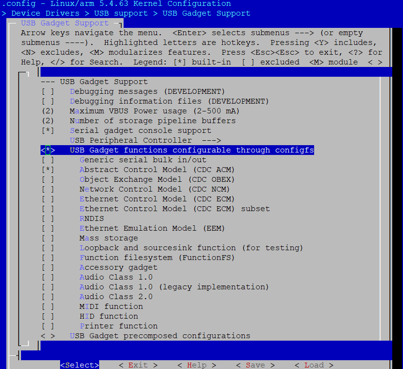
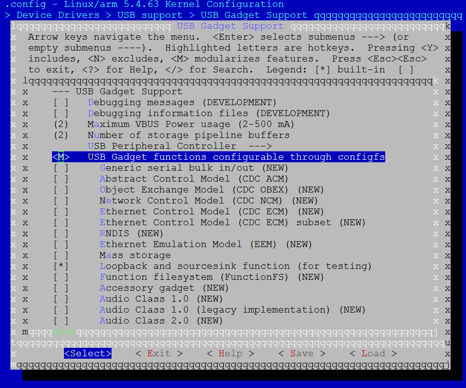
Type Y to select the following options in USB Gadget Support:
USB Gadget functions configurable through configfs
Serial gadget console support
Abstract Control Model (CDC ACM)
Module Configuration
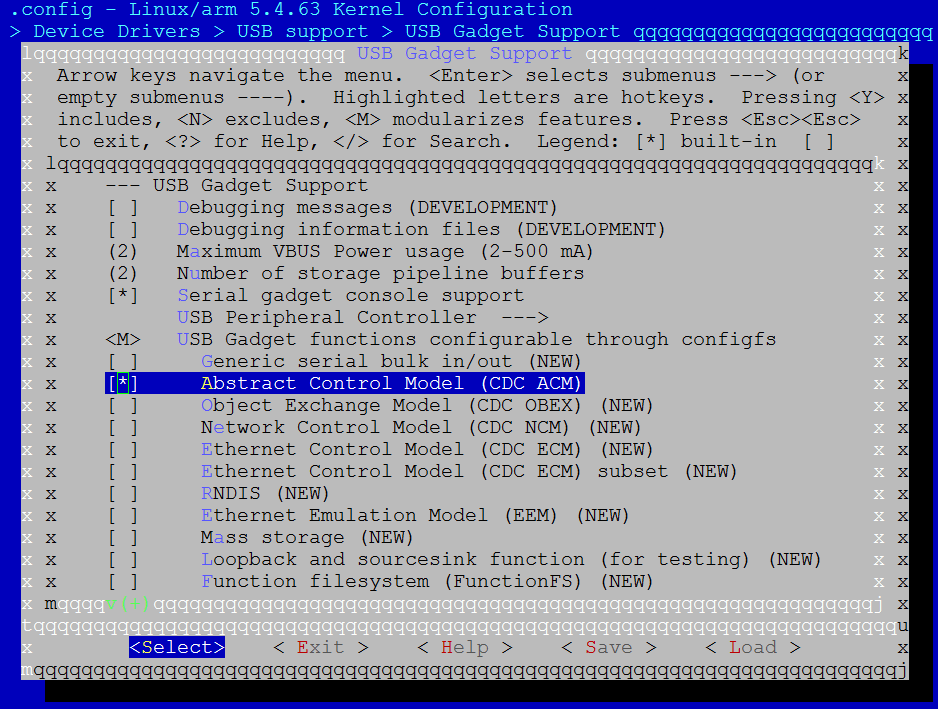
Select the following options in USB Gadget Support:
Type
Mto select USB Gadget functions configurable through configfsType
Yto select Serial gadget console supportType
Yto select Abstract Control Model (CDC ACM)
Load kernel modules about CDC ACM class after loading common USB device modules.
insmod /lib/modules/<kernel_ver>/kernel/drivers/usb/gadget/function/u_serial.ko
insmod /lib/modules/<kernel_ver>/kernel/drivers/usb/gadget/function/usb_f_acm.ko
APIs for Application
Usage Example
This example demonstrates how to configure the development board as a CDC ACM device.
Connect the development board to the PC using a USB cable.
Execute the following commands in the development board console for Configfs configuration:
mkdir /mnt/config
mount none /mnt/config -t configfs
cd /mnt/config/usb_gadget
mkdir cdc && cd cdc
echo 0x0200 > bcdUSB
echo 0x02 > bDeviceClass
echo 0x02 > bDeviceSubClass
echo 64 > bMaxPacketSize0
echo 0x8730 > idProduct
echo 0x0BDA > idVendor
mkdir strings/0x409
echo "Realtek" > strings/0x409/manufacturer
echo "VCOM" > strings/0x409/product
echo "123456789AB" > strings/0x409/serialnumber
mkdir configs/c.1
echo 120 > configs/c.1/MaxPower
mkdir configs/c.1/strings/0x409
echo "acm" > configs/c.1/strings/0x409/configuration
mkdir functions/acm.ttyS1
ln -s functions/acm.ttyS1 configs/c.1/
echo 40080000.usb > UDC
Data transmission test
Open the corresponding COM port on the PC. Enter in the development board console:
echo 12345 > /dev/ttyGS0The PC serial tool will receive the string
12345.Data reception test
Listen to the port in the development board console:
cat /dev/ttyGS0Send the string
12345from the PC; the development board terminal will display the received content.
Note
Win7 cannot drive CDC ACM device directly. Specific driver needs to be installed: <sdk>/tools/image_tool/RtkUsbCdcAcmSetup.INF. And the PID / VID in this driver should be consistent with the CDC ACM device descriptor.
Note
If PC COM cannot be opened, comment following code in <linux>/drivers/usb/gadget/function/f_acm.c for temporary workaround:
static int acm_cdc_notify(struct f_acm *acm, u8 type, u16 value,
void *data, unsigned length)
{
   /* ep_queue() can complete immediately if it fills the fifo... */
   spin_unlock(&acm->lock);
   //status = usb_ep_queue(ep, req, GFP_ATOMIC);
   spin_lock(&acm->lock);
}
HID Device Solution
Configuration
Besides the common USB device configurations, extra configurations are required to support USB HID class, and user can choose to configure it as built-in functions or independent kernel modules.
Make sure HID bus support and Generic HID driver are selected:
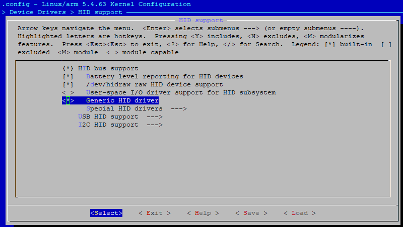
Actually, above configurations are enabled as default in SDK to support ADB.
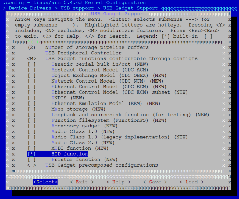
Built-in Configuration
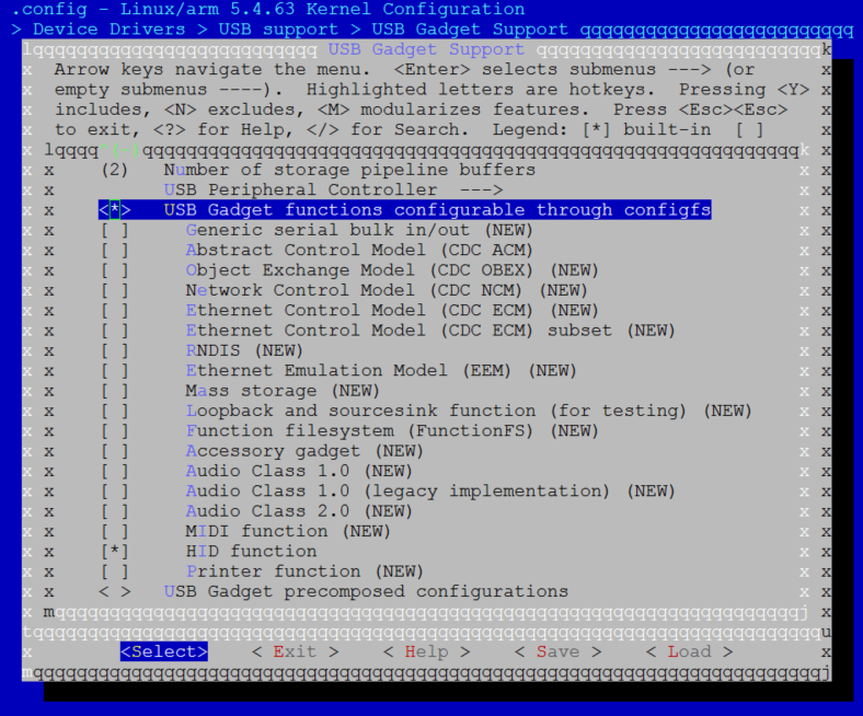
Type
Yto select the following options in USB Gadget Support:USB Gadget functions configurable through configfs
Serial gadget console support
HID function
Module Configuration
Select the following items in USB Gadget Support:
Type
Mto select USB Gadget functions configurable through configfsType
Yto select HID function
Load kernel modules about HID class after loading common USB device modules:
insmod /lib/modules/<kernel_ver>/kernel/drivers/usb/gadget/function/udc-core.ko
insmod /lib/modules/<kernel_ver>/kernel/drivers/usb/gadget/function/usb_f_hid.ko
APIs for Application
Refer to usb guide x498.
Usage Example
This example demonstrates how to configure the development board as a HID mouse device.
Configure USB device:
mkdir /mnt/config
mount none /mnt/config -t configfs
cd /mnt/config/usb_gadget
mkdir hid
cd hid
echo 0x0200 > bcdUSB
echo 0x03 > bDeviceClass
echo 0x00 > bDeviceSubClass
echo 64 > bMaxPacketSize0
echo 0x8730 > idProduct
echo 0x0BDA > idVendor
mkdir strings/0x409
echo "Realtek" > strings/0x409/manufacturer
echo "HID" > strings/0x409/product
echo "123456789AB" > strings/0x409/serialnumber
mkdir configs/c.1
echo 120 > configs/c.1/MaxPower
mkdir configs/c.1/strings/0x409
echo "Primary configuration" > configs/c.1/strings/0x409/configuration
Configure HID report descriptor:
mkdir functions/hid.usb0
echo 1 > functions/hid.usb0/subclass
echo 2 > functions/hid.usb0/protocol
echo 4 > functions/hid.usb0/report_length
echo -ne\\x05\\x01\\x09\\x02\\xa1\\x01\\x09\\x01\\xa1\\x00\\x05\\x09\\x19\\x01\\x29\\x03\\x15\\x00\\x25\\x01\\x95\\x03\\x75\\x01\\x81\\x02\\x95\\x01\\x75\\x05\\x81\\x03\\x05\\x01\\x09\\x30\\x09\\x31\\x09\\x38\\x15\\x81\\x25\\x7f\\x75\\x08\\x95\\x03\\x81\\x06\\xc0\\xc0> functions/hid.usb0/report_desc
ln -s functions/hid.usb0 configs/c.1/
echo 40080000.usb > UDC
After connecting to the host, communicate with the host via the device node
/dev/hidg0. The following command will control the mouse to move 0x40 pixels to the right and down:echo -ne "\0\x40\x40\0" > /dev/hidg0
Note
Mouse data packet protocol format:
BYTE0
|-- bit7~bit3: RSVD
|-- bit2: middle button press
|-- bit1: right button press
|-- bit0: left button press
BYTE1: x-axis value, -128~127
BYTE2: y-axis value, -128~127
BYTE3: wheel value, -128~127
Mass Storage Device Solution
Configuration
Besides the common USB device configurations, extra configurations are required to support USB mass storage class, and user can choose to configure it as built-in functions or independent kernel modules.
Built-in Configuration
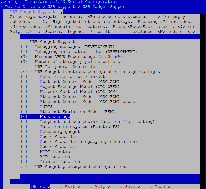
Type
Yto select the following options in USB Gadget Support:USB Gadget functions configurable through configfs
Mass storage
Module Configuration
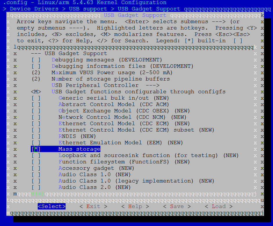
Select the following items in USB Gadget Support:
Type
Mto select USB Gadget functions configurable through configfsType
Yto select Mass storage
Load kernel modules about MSC class after loading common USB device modules.
insmod /lib/modules/<kernel_ver>/kernel/drivers/usb/gadget/function/udc-core.ko
insmod /lib/modules/<kernel_ver>/kernel/drivers/usb/gadget/function/usb_f_mass_storage.ko
insmod /lib/modules/<kernel_ver>/kernel/drivers/usb/gadget/function/libcomposite.ko
APIs for Application
Refer to usb guide x498.
Usage Example
This example demonstrates how to configure the development board as a USB MSC device and use an SD card as the storage medium.
Configure SD card of the board, refer to Chapter SDIO Host for details.
Connect the development board to the PC.
Execute configuration commands in the development board console:
mkdir /mnt/config
mount none /mnt/config -t configfs
cd /mnt/config/usb_gadget
mkdir msc && cd msc
echo 0x0200 > bcdUSB
echo 0x8730 > idProduct
echo 0x0BDA > idVendor
mkdir strings/0x409
echo "Realtek" > strings/0x409/manufacturer
echo "MSC" > strings/0x409/product
echo "123456789AB" > strings/0x409/serialnumber
mkdir configs/c.1
echo 120 > configs/c.1/MaxPower
mkdir configs/c.1/strings/0x409
echo "mass_storage" > configs/c.1/strings/0x409/configuration
mkdir functions/mass_storage.0
echo /dev/mmcblk0 >functions/mass_storage.0/lun.0/file
echo 1 > functions/mass_storage.0/lun.0/removable
echo 0 > functions/mass_storage.0/lun.0/nofua
ln -s functions/mass_storage.0 configs/c.1/
echo 40080000.usb > UDC
After successful configuration, the PC will identify a new removable disk (UDISK).
Vendor-Specific Device Solution
Vendor class is designed for user to develop customized USB device class.
Configuration
Besides the common USB device configurations, extra configurations are required to support USB vendor class driver, and user can choose to configure it as built-in functions or independent kernel modules.
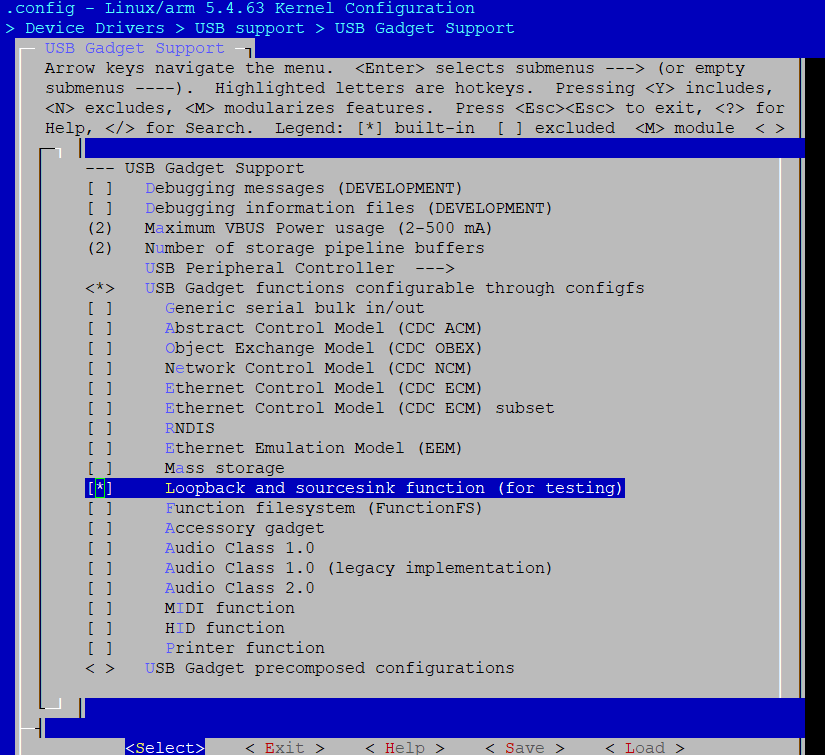
Built-in Configuration
Type
Yto select the following options in USB Gadget Support:USB Gadget functions configurable through configfs
Loopback and sourcesink function (for testing)
Module Configuration
Select the following options in USB Gadget Support:
Type
Mto select USB Gadget functions configurable through configfsType
Yto select Loopback and sourcesink function (for testing)
Load kernel modules about vendor class after loading common USB device modules.
insmod /lib/modules/<kernel_ver>/kernel/drivers/usb/gadget/function/udc-core.ko
insmod /lib/modules/<kernel_ver>/kernel/drivers/usb/gadget/function/usb_f_ss_lb.ko
insmod /lib/modules/<kernel_ver>/kernel/drivers/usb/gadget/function/libcomposite.ko
APIs for Application
None.
Usage Example
The following steps demonstrate how to test the Gadget Vendor class functionality:
Execute configuration commands in the development board console:
mkdir /mnt/config
mount none /mnt/config -t configfs
cd /mnt/config/usb_gadget
mkdir vendor && cd vendor
echo 0x0200 > bcdUSB
echo 0xa4a0 > idProduct
echo 0x0525 > idVendor
mkdir strings/0x409
echo "Realtek" > strings/0x409/manufacturer
echo "Vendor" > strings/0x409/product
echo "123456789AB" > strings/0x409/serialnumber
mkdir configs/c.1
mkdir configs/c.2
echo 120 > configs/c.1/MaxPower
echo 120 > configs/c.2/MaxPower
mkdir configs/c.1/strings/0x409
mkdir configs/c.2/strings/0x409
echo "vendor1" > configs/c.1/strings/0x409/configuration
echo "vendor2" > configs/c.2/strings/0x409/configuration
mkdir functions/SourceSink.0
mkdir functions/Loopback.0
ln -s functions/SourceSink.0 configs/c.1/
ln -s functions/Loopback.0 configs/c.2/
echo 40080000.usb > UDC
Note
This example is configured as a composite device:
ln -s functions/SourceSink.0 configs/c.1/ indicates the default function is sourcesink.
ln -s functions/Loopback.0 configs/c.1/ indicates the default function is loopback.
Connect the development board to the USB Host.
Perform Host Vendor and Device Vendor interaction tests (using the
testusbtool):Function
loopback
sourcesink
Config fs setting
ln -s functions/Loopback.0 configs/c.1/
ln -s functions/SourceSink.0 configs/c.1/
Host console command
testusb -a -c1 -t30 -s256 -g32 -v1
testusb -a -c1 -tx -s256 -g32 -v1
Device console command
No need command
No need command
Note
In the host test command:
Case 30 (
-t30) is used to test the loopback function.Case 0~29 (
-tx, where x represents a number between 0~29) is used to test the sourcesink function, and parameters can be modified by the user.