Introduction
The Unmanned Peripheral System (UPS) can be regarded as a network that lets the different peripheral modules communicate directly with each other without the participation of MCU. With UPS, the participation of software can be minimized to avoid the time error caused by software operation while realizing the control of light dimming. The two sides communicating through UPS are called producer and consumer, among which the producer is the peripheral module sending out signal, and the consumer is another peripheral module that applies corresponding actions according to the received signal. For the scenario of multiple producers transmitting signals to the same consumer, the consumer required signal source can be selected by configuring the PRS_SRC_SEL field in REG_PRS_CTRL.
Features
Producer and Consumer
Configurable signal source
Configurable input reverse
Positive edge detection
Various dimming signal types
Block Diagram

Functional Description
Timer
Timer can be used for time counting. The following figures are the block diagram of timer and the timing diagram of timer.
Timer works as below:
If timer detects a high level in a terminal, the counter inside timer counts up from 0.
If the counter value CNT reaches the max. value, the counter overflows and the of_out signal changes from low level to high level. Meanwhile, the counter continues to count from 0.
After counting for a clock cycle, hardware will pull down the of_out signal.
If timer detects a low level in a terminal, counter stops working and CNT retains. After enabled, the timer continues counting.


Note
In the practical application of UPS, TIM10 is used as the fixed timer.
Deglitch Filter
In order to reduce the impact of signal glitches on the digital circuit, the deglitch filter is used to debounce signal with XTAL_40MHz sampling clock. The larger the dbc_cnt is, the wider the deglitch can be filtered, and the longer the delay will be. For different UPS signal sources, adjusting the value of dbc_cnt appropriately can filter glitches and minimize the delay caused by digital filtering at the same time.
Edge Detection
The following figure is the block diagram of edge detection. The input signals of edg_dtc module include clk, start_in and stop_in, and the output is dtc_out.
edg_dtc module works as below:
edg_dtc detects the rising edges of start_in and stop_in.
When a rising edge is detected in start_in, edg_dtc pulls up the dtc_out signal after a clock cycle.
When a rising edge is detected in stop_in, edg_dtc pulls down the dtc_out signal after a clock cycle; otherwise, the dtc_out signal stays high.

The timing diagram of edge detection is shown in the following figure.

Signal Reverse
External ZCD signals and CMP outputs can both be positive pulse or negative pulse. When it is a positive pulse signal, the system works normally; when it is a negative pulse signal, rvs_en is configured to 1 to reverse the negative pulse signal to ensure the normal operation of the system.
Dimming Signal Types
In order to meet various demands, three kinds of dimming control signals can be realized by adjusting the parameters of the PWM timer.
OPM_DefaultLevelx = low, CCxPolarity = active_low: Pull down the control signal before the second zero-crossing point.
OPM_DefaultLevelx = high, CCxPolarity = active_low: Pull down the control signal at the second zero-crossing point.
OPM_DefaultLevelx = high, CCxPolarity = active_high: Pull down the control signal after the second zero-crossing point.

Registers
The base address of UPS registers is 0x4100_C200.
Name |
Address offset |
Access |
Description |
|---|---|---|---|
REG_PRS_CTRL |
0C4h |
R/W |
UPS Control Register |
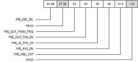
REG_PRS_CTRL
Name: UPS Control Register
Size: 32 bits
Address offset: 0C4h
Read/write access: R/W
Bit |
Symbol |
Access |
Reset |
Description |
|---|---|---|---|---|
31:28 |
PRS_SRC_SEL |
R/W |
0 |
UPS trigger source selection
|
27:22 |
RSVD |
0 |
Reserved |
|
21 |
PRS_OUT_PWM_TRIG |
R/W |
0 |
Enable for output trigger to PWM |
20 |
PRS_OUT_TIM_EN |
R/W |
0 |
Enable for output a signal to basic timer |
19 |
PRS_IN_TIM_OF |
R/W |
0 |
Enable for basic timer overflow input |
18 |
PRS_RVS_EN |
R/W |
0 |
Invert polarity for UPS input 0: Positive edge polarity 1: Negative edge polarity |
17:2 |
PRS_DBC_CNT |
R/W |
0 |
Debounce count for UPS function |
1:0 |
RSVD |
0 |
Reserved |