Getting Started
Ameba Arduino makes it simple to start building IoT projects. With full support for the Arduino IDE, you can quickly set up your development environment, connect an evaluation board, and run your first sketch. The platform provides easy access to Wi-Fi, BLE, and other core functions, along with flexible peripheral interfaces, allowing you to experiment with sensors, actuators, and smart device features immediately.
Follow the steps below to select your board, install the necessary tools, and begin developing your IoT applications.
Get Evaluation Boards
Realtek Ameba Arduino evaluation boards provide a ready-to-use platform for exploring the capabilities of Ameba SoCs. Each board comes with pre-connected peripherals, built-in Wi-Fi and BLE, and easy access to GPIOs and other interfaces. These boards allow developers to quickly prototype, test, and validate IoT projects without needing to design custom hardware.
Choose the board that best fits your project requirements to start experimenting with wireless connectivity, sensors, and other IoT functionalities immediately.
AMB82-mini EVB
AMB82-mini (Ameba RTL8735B) |
|
|


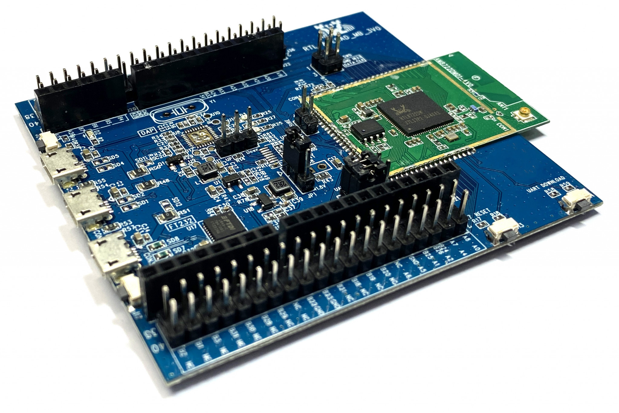
AMB21 / AMB22 EVB
AMB21 / AMB22 (Ameba RTL8722DM / RTL8722CSM) |
|
|
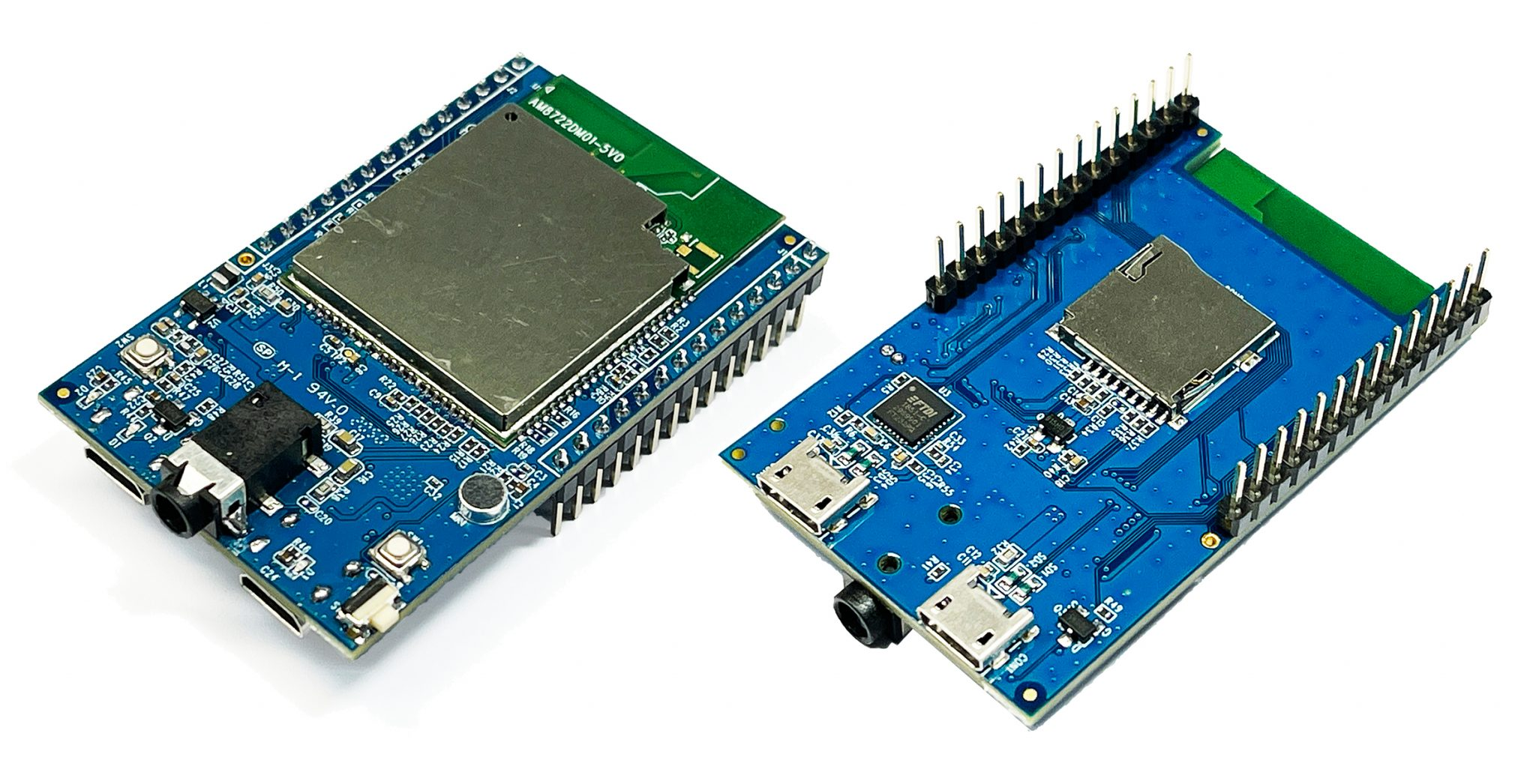
AMB23 EVB
AMB23 (Ameba RTL8722DM) |
|
|
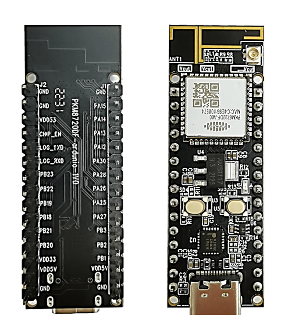
AMB25 EVB
AMB25 (Ameba RTL8720DF) |
|
|
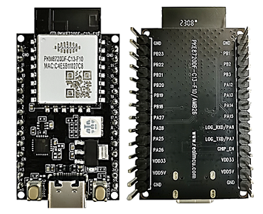
AMB26 EVB
AMB26 (Ameba RTL8720DF) |
|
|
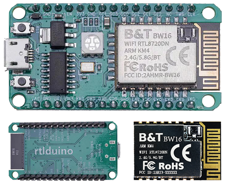
BW16 EVB
BW16 (Ameba RTL8720DN) by Ai-Thinker |
|
|
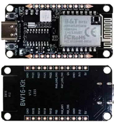
BW16-TypeC Arduino
BW16 type C (Ameba RTL8720DN) by Ai-Thinker |
|
|
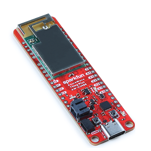
AW-CU488 EVB
AW-CU488 Thing Plus (Ameba RTL8721DM) by SparkFun |
|
|
Software Installation
Set up Arduino IDE
Arduino IDE supports third-party hardware. Arduino IDE can be downloaded from offcial Arduino website and documents refer to Getting Started with Arduino IDE 2
When the installation is finished, open Arduino IDE and go to File -> Preferences
Paste the following URL into Additional Boards Manager URLs field:
Stable release link:
https://github.com/Ameba-AIoT/ameba-arduino-pro2/raw/main/Arduino_package/package_realtek_amebapro2_index.jsonEarly release link:
https://github.com/Ameba-AIoT/ameba-arduino-pro2/raw/dev/Arduino_package/package_realtek_amebapro2_early_index.jsonhttps://ameba-doc-arduino-sdk-json.readthedocs-hosted.com/en/latest/_static/package_realtek_amebapro2_early_index_rtd.json
Stable release link:
https://github.com/Ameba-AIoT/ameba-arduino-d/raw/master/Arduino_package/package_realtek_amebad_index.jsonEarly release link:
https://github.com/Ameba-AIoT/ameba-arduino-d/raw/dev/Arduino_package/package_realtek_amebad_early_index.json
Next, go to Tools -> Board -> Boards Manager
The Boards Manager requires about 10 ~ 20 seconds to refresh all hardware files (if the network is in bad condition, it may take longer).
Find Realtek Ameba Boards in the list, chose the right Package/SDK and click Install, then the Arduino IDE starts to download required files.
After the installation successfully, the Arduino IDE is ready for Ameba SDK.
Connect Ameba Board
Connect Ameba EVB to the computer via USB.
Note
Differnet boards may have different USB ports. For example, Micro USB or USB TypeC.
If this is the first time connects board to computer, the USB driver for board will be automatic installed.
Next, at IDE menu, go to tools -> Board. Then select the board going to use.
Go to tools -> Port Then select the port of the board.
If you have driver issue of connect board to computer please install the USB driver manually.
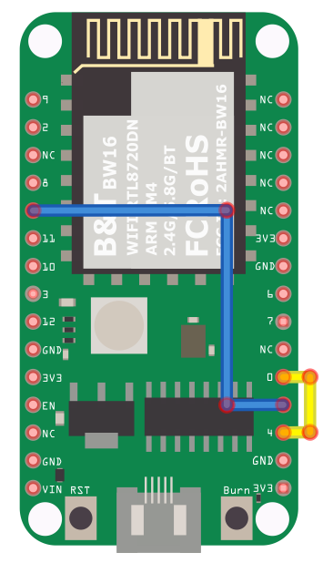
Refer to the BW16 pinmap/layout D0 and D1 pins are used for program uploading. However, onboard USB-to-UART module is connected to D4 and D5 which is not able to be directly used for program upload.

In order to upload firmware, it suggests that adding an external USB-to-UART module connecting to D0 and D1 as shown in the pin connection below:
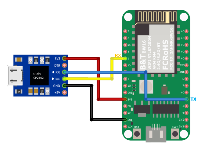
The USB driver installation depends on the USB-to-UART Chip of the external USB-to-UART module.
Optionally, the onboard USB-to-UART Chip is still usable, by connecting the pins indicated below to use the on-board USB:
D1 — D5
D0 — D4
Then install the USB driver, USB driver for CH340 USB-to-UART Chip
Check the COM port number:
Using PowerShell:
mode
List common serial (COM) devices:
ls /dev/ttyS* /dev/ttyUSB* /dev/ttyACM* 2>/dev/null
Or check kernel messages after plugging in the device:
dmesg | grep tty
List macOS serial ports:
ls /dev/tty.*
ls /dev/cu.*
Filter only USB-related serial devices:
ls /dev/tty.* | grep usb
Compile and Run
Compile and Upload
Arduino IDE provides many built-in examples, which can be compiled, uploaded, and run directly on the boards. Here, take the Blink example as the first try.
Open File -> Examples -> 01.Basics -> Blink
Next, we compile the sample code directly; click Sketch -> Verify/Compile
Arduino IDE prints the compiling messages in the bottom area of the IDE window. When the compilation is finished.
Then make sure board is connected to computer, then click Sketch -> Upload
The Arduino IDE will compile first then upload. Users are required to enter the upload mode of the board. To enter upload mode, first press and hold the UART_DOWNLOAD button, then press and release the RESET button, lastly release the UART_DOWNLOAD button.
Button Functions |
Button Process |
|---|---|
Reset board |
|
Enter upload mode |
|
Note
Different boards/modules ay have different button layout, please refer to the pinmap/layout of the boards/modules.
Some boards may have the hardware updates and enabled IDE menu option Auto Flash Mode, please ignore above manual instruction.
It is optional for users to check if the board entered the upload mode. Open serial monitor/terminal and check the information/logs print out.
Note
Default baud rate of serial monitor/terminal should be set to 115200.
Different boards/modules ay have different information/logs print out, but there should be information/logs if upload success.
When upload completed, the Done uploading message is printed by Arduino IDE.
Run the Blink example
In each basic example, Arduino not only provides sample code, but also detailed documentation, including wiring diagram, sample code explanation, technical details, …etc. Please refer the detailed information of the Blink example: https://www.arduino.cc/en/Tutorial/Blink
Ameba Boards are beyond the basic blink example, please refer to Arduino Example Guide and Arduino API document to dig more.
Connect all componments for Blink example.
This example makes on-board LED blinks.
Or use external LED. Set any GPIO pins as signal output then connects to the external LED.
Refers to Basic Example / Arduino-build-in example
Use external LED. Set any GPIO pins as signal output then connects to the external LED.
Refers to Basic Example / Arduino-build-in example
This example makes on-board LED blinks (green or blue).
Or use external LED. Set any GPIO pins as signal output then connects to the external LED.
Refers to Basic Example / Arduino-build-in example
Use external LED. Set any GPIO pins as signal output then connects to the external LED.
Refers to Basic Example / Arduino-build-in example
This example makes on-board RGB LED blinks.
Or use external LED. Set any GPIO pins as signal output then connects to the external LED.
Refers to Basic Example / Arduino-build-in example
This example makes on-board RGB LED blinks.
Or use external LED. Set any GPIO pins as signal output then connects to the external LED.
Refers to Basic Example / Arduino-build-in example
This example makes on-board RGB LED blinks.
Or use external LED. Set any GPIO pins as signal output then connects to the external LED.
Refers to Basic Example / Arduino-build-in example
This example makes on-board LED blinks (blue).
Or use external LED. Set any GPIO pins as signal output then connects to the external LED.
Refers to Basic Example / Arduino-build-in example
Press RESET button of the board every time finish the upload or start running the application.