Getting Started
Board Introduction
AMBG2 board is shown in following figure.
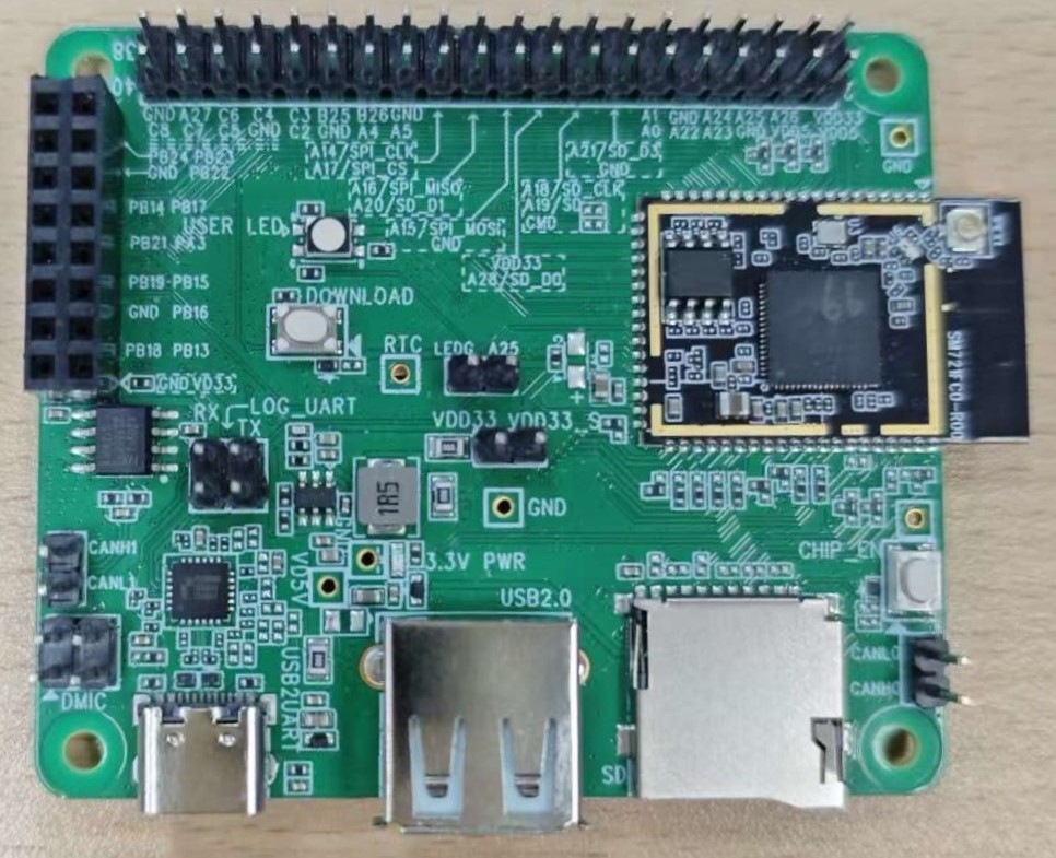
AMBG2 board
Please refer to the following figure and table for the pin diagram and functions.

AMBG2 pins
Arduino Pin |
GPIO Pin |
GPIO INT |
ADC |
PWM |
UART |
SPI |
I2C |
|---|---|---|---|---|---|---|---|
D0 |
PA_2 |
√ |
√ |
||||
D1 |
PB_20 |
√ |
√ |
||||
D2 |
PA_26 |
√ |
√ |
||||
D3 |
PA_25 |
√ |
√ |
||||
D4 |
PA_24 |
√ |
|||||
D5 |
PA_23 |
√ |
|||||
D6 |
PA_22 |
√ |
|||||
D7 |
PA_21 |
√ |
|||||
D8 |
PA_18 |
√ |
|||||
D9 |
PA_19 |
√ |
|||||
D10 |
PA_28 |
√ |
|||||
D11 |
PA_15 |
√ |
√ |
||||
D12 |
PA_16 |
√ |
√ |
||||
D13 |
PA_20 |
√ |
|||||
D14 |
PA_14 |
√ |
√ |
√ |
|||
D15 |
PA_17 |
√ |
√ |
√ |
|||
D16 |
PA_5 |
√ |
|||||
D17 |
PB_26 |
√ |
√ |
||||
D18 |
PA_4 |
√ |
√ |
||||
D19 |
PB_25 |
√ |
√ |
||||
D20 |
PA_27 |
√ |
√ |
||||
D21 |
PB_24 |
√ |
|||||
D22 |
PB_23 |
√ |
|||||
D23 |
PB_22 |
√ |
|||||
D24 |
PB_14 |
√ |
√ |
||||
D25 |
PB_17 |
√ |
|||||
D26 |
PB_21 |
√ |
|||||
D27 |
PA_3 |
√ |
|||||
D28 |
PB_19 |
√ |
|||||
D29 |
PB_15 |
√ |
√ |
||||
D30 |
PB_16 |
√ |
√ |
||||
D31 |
PB_18 |
√ |
|||||
D32 |
PB_13 |
√ |
√ |
Set Up Developing Environment
OS environment
AMBG2 (RTL8721F) board currently supports Windows OS 64-bits, Linux OS (Ubuntu) and macOS. To have the best experiences, please use the latest version of OS.
Installing the driver
First, connect AMBG2 to the computer via USB Type-C to Type-A cable.
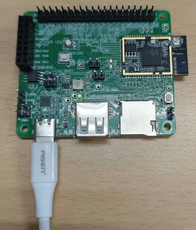
Connect AMBG2 board to computer
If this is the first time connects AMBG2 to computer, the USB driver for AMBG2 will be automatically installed.
If you have driver issue of connect board to computer please go to https://www.prolific.com.tw/ for USB driver.
Check the COM port number in Device Manager of computer.
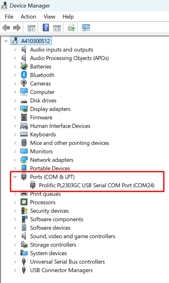
Check COM port number
Set up Arduino IDE
From version 1.6.5, Arduino IDE supports third-party hardware. Therefore, we can use Arduino IDE to develop applications, and the Arduino basic examples can run on AMBG2 too.
Arduino IDE can be downloaded in the Arduino website: https://www.arduino.cc/en/software
When the installation is finished, open Arduino IDE.
To set up AMBG2 correctly in Arduino IDE, go to
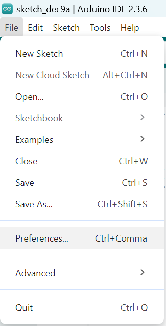
And paste the following URL into Additional boards manager URLs field:
https://github.com/Kyderio/arduino_test/raw/master/Arduino_package/package_realtek_test_index.json
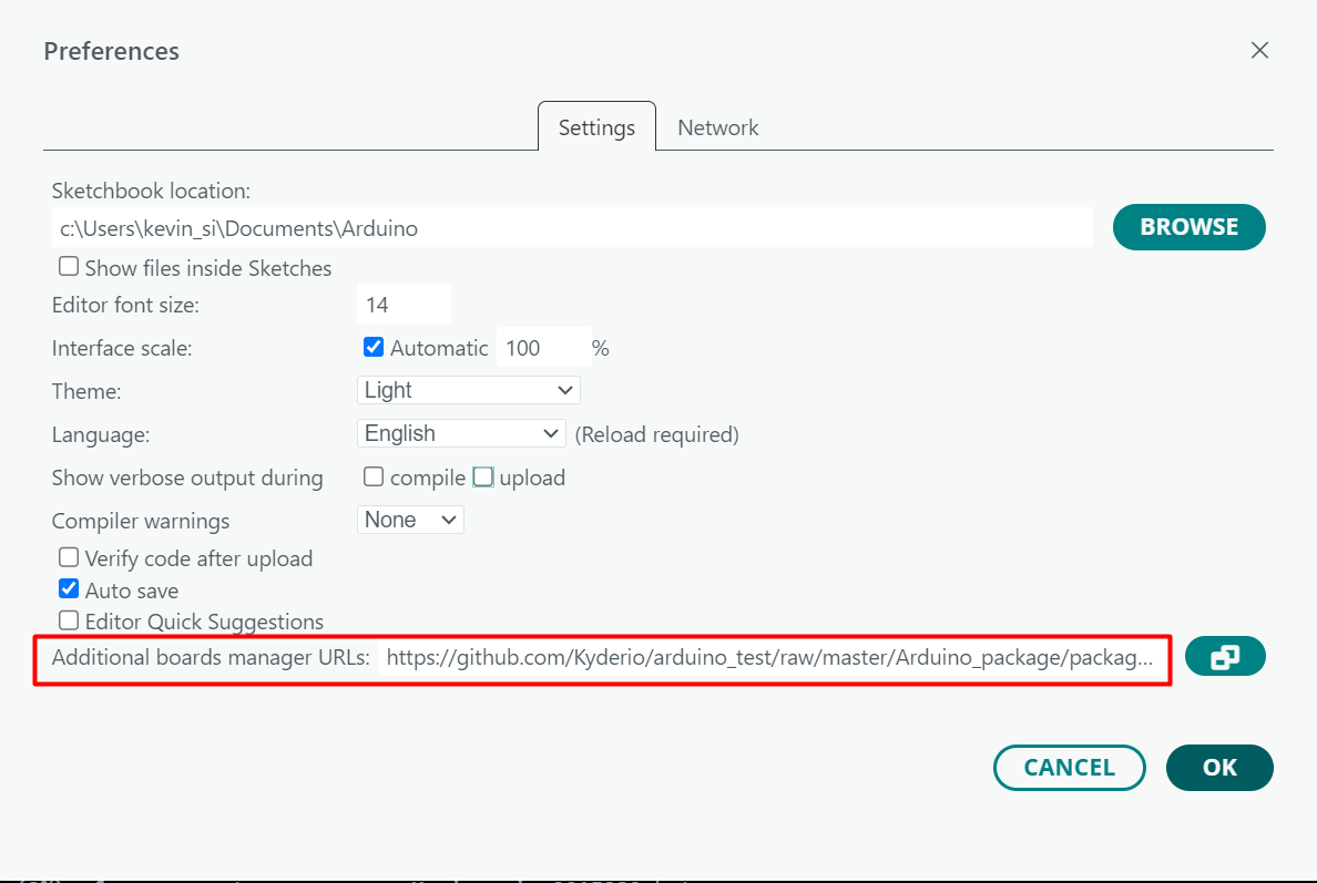
Add Additional boards manager URLs
Next, go to
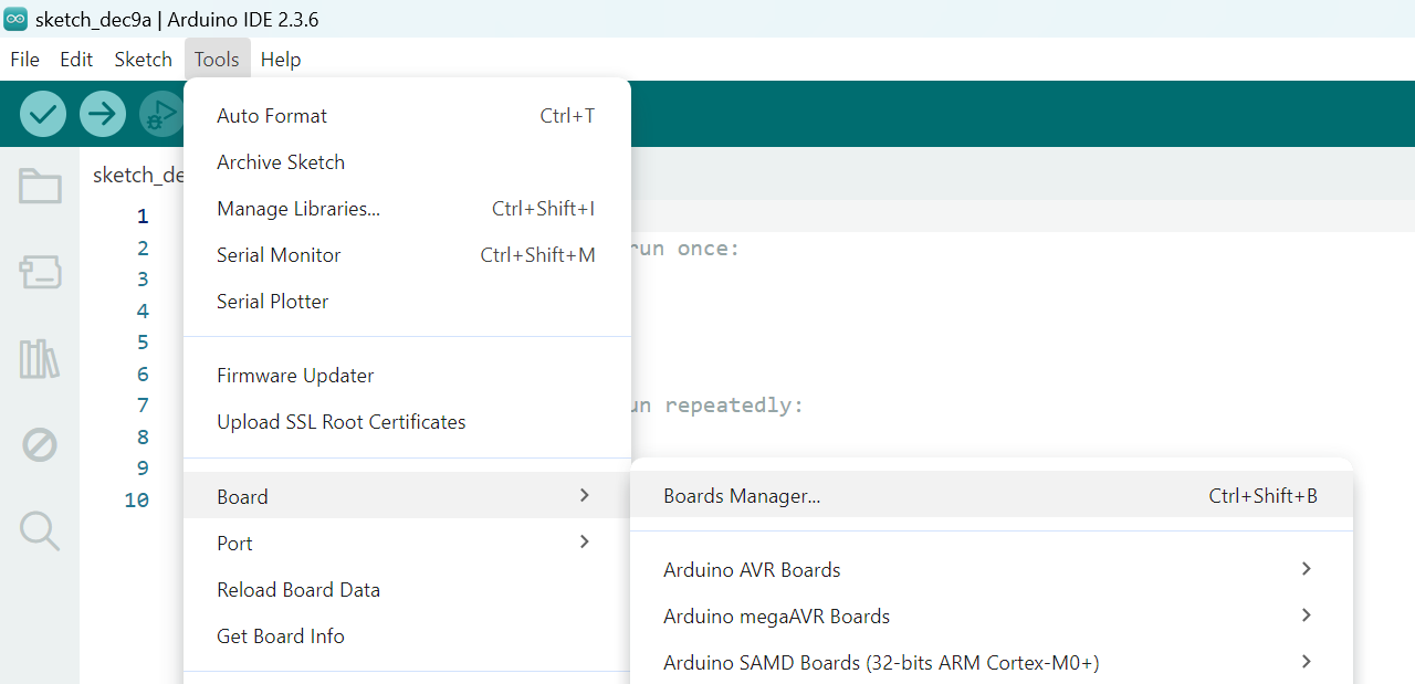
Go to boards manager
Enter realtek in the search box, find Realtek Test Boards (32-bit ARM Cortex-M33 @200MHz) from the filtered list, select the desired version from the dropdown menu, and click INSTALL, then the Arduino IDE starts to download required files.
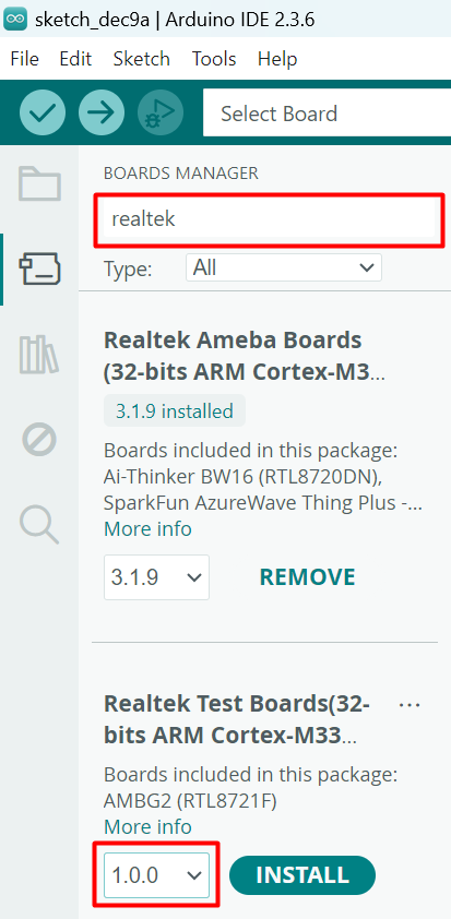
Install board in BOARD MANAGER
After installing, we select board via
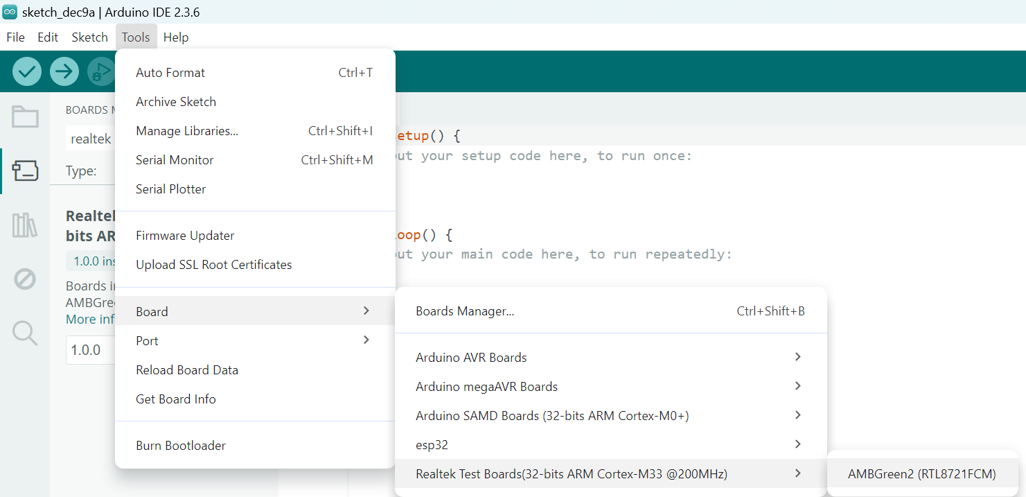
Select board
Setup port
Click , select the corresponding port from the dropdown menu.
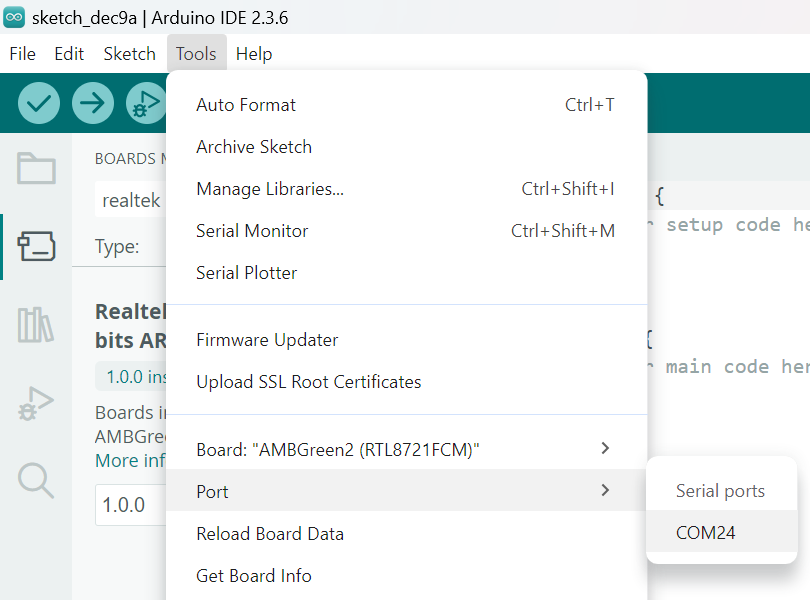
Select port
Try the First Example
Compile
Arduino IDE provides many built-in examples, which can be compiled, uploaded and run directly on the boards. Here, we take the Blink example as the first try.
Open
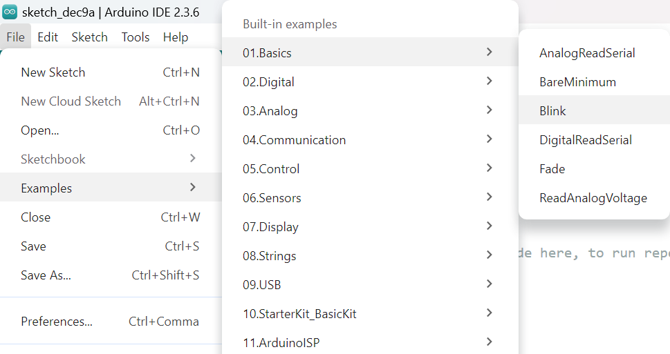
Select blink example
Arduino IDE opens a new window with the complete sample code.
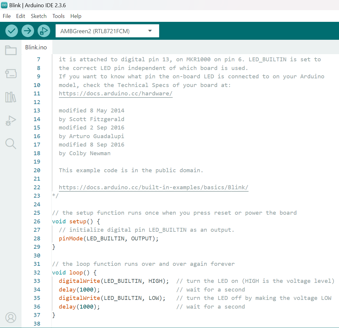
Blink example
Next, we compile the sample code directly, click
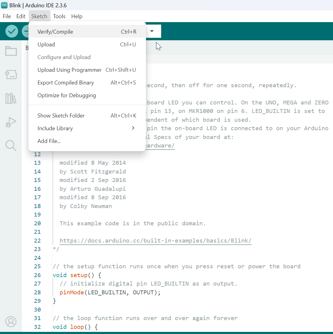
Click Verify/Compile
Arduino IDE prints the compiling messages in the bottom area of the IDE window. When the compilation is finished, you will get the message as following.

Compiling done
Upload
Afterwards, we will upload the compiled code to board.
Please make sure board is connected to computer, then click
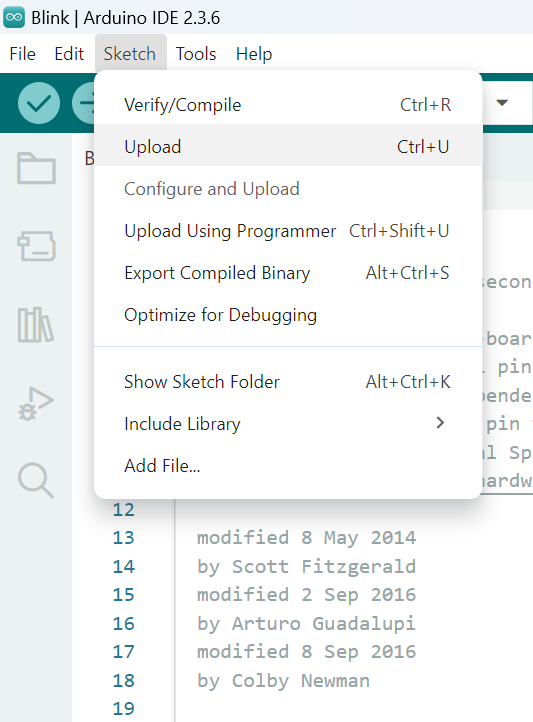
Click upload
The Arduino IDE will compile first then upload. Users are required to enter the upload mode of the board. To enter upload mode, first press and hold the DOWNLOAD button, then press and release the CHIP_EN button, lastly release the DOWNLOAD button.
Again, during the uploading procedure the IDE prints messages. When upload completed, the Done uploading message is printed
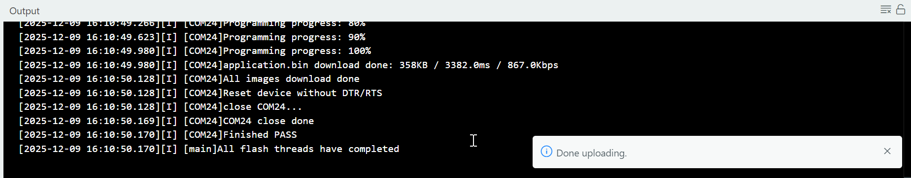
Uploading done
Run the Blink example
In short, this example makes LED blinks, and it uses LED_BUILTIN (refer to the pin diagram D5). Then we connect the LED as the following figure. It is recommended to use a resister with suitable resistance in series between LED and GND.
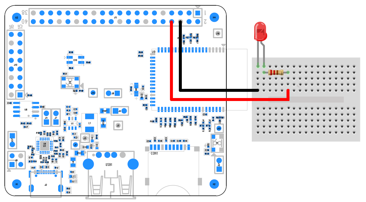
Connect the LED and resistance
Finally, press the CHIP_EN button, and you can see the LED blinking.