Introduction
General Direct Memory Access (GDMA) Controller, also known as DMAC, is used to transfer data between memory and peripherals. The data transfer process does not require CPU intervention, thereby reducing the CPU workload. The architecture diagram of GDMA is shown below:

GDMA supports the following features:
Supports up to 8 independent channels. The source and destination ports of each channel can be freely assigned to Memory or peripherals with GDMA capability.
Supports channel priority configuration.
Supports multiple transfer directions:
Peripheral to Memory
Peripheral to Peripheral
Memory to Peripheral
Memory to Memory
Each channel is equipped with an independent FIFO. The FIFO size varies across channels to suit different application scenarios.
Flexible flow control options: users can configure the transfer request and pacing to be controlled by the source peripheral, destination peripheral, or the DMAC itself.
Supports both single and burst transfer modes.
Supports single block and multiple block data transfers.
Supports secure transfer mode.
Supports low power consumption operation.
Supports pause, resume, and disable of channels during data transfers without data loss.
Supports gather transfer for non-contiguous memory (Channel 0 ~ Channel 3).
Supports scatter transfer for contiguous memory (Channel 0 ~ Channel 3).
DMAC Configuration
The general DMA configuration process is as follows:
Initialize clock: Enable DMA controller (DMAC) clock
Configure relevant DMA channel
Allocate a free DMA channel
Set channel control parameters according to application requirements
Transfer direction and flow control: such as memory-to-peripheral, peripheral-to-memory, and whether the source or destination peripheral or DMAC controls transfer requests and pace
Source port and destination port addresses
Transfer width (1/2/4 Bytes)
Transfer mode (1/4/8/16)
Transfer block size (Block Size)
Priority setting
Enable channel interrupt (for transfer complete/error notification, if needed)
Start data transfer: Set channel enable bit, start DMA channel, peripheral/DMAC initiates DMA request, and begin data movement
Completion and post-processing
DMA transfer generates an interrupt after completion
Handle completion signal and release resources in the interrupt service routine
DMA parameter illustration:

Channel Allocation and Release
DMA implements channel allocation and release through the following two APIs:
GDMA_ChnlAlloc(): Allocates channels sequentially, starting from channel 0.GDMA_ChnlFree(): Releases a channel according to the specified channel number.
During the channel allocation process, it is possible that two CPUs may request the same channel simultaneously, which can cause the program to run abnormally. To solve this issue, a hardware SEMA is used for protection during the channel allocation process.
Transfer Direction and Flow Controller
There are currently four transfer directions and two flow controller settings, resulting in eight available configurations.
When the peripheral is set as the flow controller, the DMA transfers data based on the single/burst requests from the peripheral.
When the DMAC is set as the flow controller, all requests from the peripheral will be processed according to the configured request type.
TT_FC[2:0] field of CTLx register (x is channel) |
Direction |
Flow Controller |
|---|---|---|
000 |
Memory to Memory |
DMAC |
001 |
Memory to Peripheral |
DMAC |
010 |
Peripheral to Memory |
DMAC |
011 |
Peripheral to Peripheral |
DMAC |
100 |
Peripheral to Memory |
Peripheral |
101 |
Peripheral to Peripheral |
Source Peripheral |
110 |
Memory to Peripheral |
Peripheral |
111 |
Peripheral to Peripheral |
Destination Peripheral |
Principles of Flow Controller Configuration:
If the block_ts is known, use DMAC as the flow controller. For example: music playback, image display, and memory copy operations.
If the block_ts is unknown, use the peripheral as the flow controller. For example: when UART receives variable-length data, UART can be set as the flow controller so that a transfer is requested each time data arrives.
Warning
The block_ts parameter can only be set when DMAC is used as the flow controller.
When using a peripheral as the flow controller, make sure that the IP supports triggering DMA requests in the hardware design. For more details, please refer to the Handshake section.
Data Block Size
The above diagram illustrates the configuration of the GDMA transfer data size. block_ts specifies the amount of data to be transferred in a single data block and should be set to total data size/SRC_TR_WIDTH, with a maximum value of {{IC_PARAM_GDMA_BLOCK_SIZE}}.
The above diagram illustrates the configuration of the GDMA transfer data size. block_ts specifies the amount of data to be transferred in a single data block and should be set to total data size/SRC_TR_WIDTH, with a maximum value of {{IC_PARAM_GDMA_BLOCK_SIZE}}.
The above diagram illustrates the configuration of the GDMA transfer data size. block_ts specifies the amount of data to be transferred in a single data block and should be set to total data size/SRC_TR_WIDTH, with a maximum value of {{IC_PARAM_GDMA_BLOCK_SIZE}}.
The above diagram illustrates the configuration of the GDMA transfer data size. block_ts specifies the amount of data to be transferred in a single data block and should be set to total data size/SRC_TR_WIDTH, with a maximum value of {{IC_PARAM_GDMA_BLOCK_SIZE}}.
The above diagram illustrates the configuration of the GDMA transfer data size. block_ts specifies the amount of data to be transferred in a single data block and should be set to total data size/SRC_TR_WIDTH, with a maximum value of {{IC_PARAM_GDMA_BLOCK_SIZE}}.
The above diagram illustrates the configuration of the GDMA transfer data size. block_ts specifies the amount of data to be transferred in a single data block and should be set to total data size/SRC_TR_WIDTH, with a maximum value of {{IC_PARAM_GDMA_BLOCK_SIZE}}.
Transaction Mode and Width
The transaction size for each GDMA transfer can be configured:
msize > 1: Burst transfer
msize = 1: Single transfer
SRC_MSIZE[2:0]/DEST_MSIZE[2:0] field of CTLx register |
Transfer msize |
|---|---|
000 |
1 |
001 |
4 |
010 |
8 |
011 |
16 |
100 and above |
Not supported |
GDMA supports the following transfer widths:
SRC_TR_WIDTH[2:0]/DST_TR_WIDTH[2:0] of CTLx register |
Transfer Width (bytes) |
|---|---|
000 |
1 |
001 |
2 |
010 |
4 |
011 and above |
Not supported |
When DMAC acts as the flow controller, if the remaining data in a block is not enough for a Msize * Width transfer but is sufficient for a 1 * Width transfer, DMAC will initiate a single transfer request to complete the transfer.
When the peripheral is the flow controller, the peripheral decides whether to issue a single transfer or burst transfer request.
Note
When accessing peripheral: SRC_TR_WIDTH/DST_TR_WIDTH should be set according to the data width of the peripheral.
When accessing memory:
If cache is disabled, the memory address does not need to be aligned, but the total data must be divisible by SRC_TR_WIDTH to ensure block_ts remains an integer.
If cache is enabled, the memory address must meet the buffer boundary alignment and align to the cache line.
When the source or destination is memory (e.g., P2M, M2M modes): the DST_TR_WIDTH or SRC_TR_WIDTH parameter for memory will be ignored. Actual read/write operations always use the bus width (default is 32 bits, i.e., 4 bytes).
To prevent FIFO underflow or overflow, SRC_MSIZE * SRC_TR_WIDTH and DST_MSIZE * DST_TR_WIDTH must remain equal.
Transfer Types
GDMA supports the following transfer types:
Single Block: Contains only one data block
Multi-Block: Contains multiple data blocks
Auto-reloading mode
Linked-list mode
The usage scenarios and features of each mode are as follows:
Mode |
Sub-mode |
Application Scenario |
Features |
|---|---|---|---|
Single Block |
Continuous address space, single transfer |
|
|
Multi-Block |
auto-reload |
Continuous address space where the source or destination needs to repeatedly reload a particular data block |
|
link-list |
Non-contiguous address space |
|
|
continuous |
Continuous data block in a single address space |
|
Auto-reloading Mode
In auto-reloading mode, the source and destination can independently select which method to use.
Auto-reloading transfer types |
Setting |
Introduction |
|---|---|---|
Src auto reload |
PGDMA_InitTypeDef->GDMA_ReloadSrc = 1 PGDMA_InitTypeDef->GDMA_ReloadDst = 0 |
For multi-block transfers, the SAR register can be auto-reloaded from the initial value at the end of each block, and DST address is contiguous, as shown in Multi-block DMA transfer with source address auto-reloaded and contiguous destination address.. |
Dst auto reload |
PGDMA_InitTypeDef->GDMA_ReloadSrc = 0 PGDMA_InitTypeDef->GDMA_ReloadDst = 1 |
For multi-block transfers, the DAR register can be auto-reloaded from its initial value at the end of each block, and the SRC address is contiguous. |
Src & Dst auto reload |
PGDMA_InitTypeDef->GDMA_ReloadSrc = 1 PGDMA_InitTypeDef->GDMA_ReloadDst = 1 |
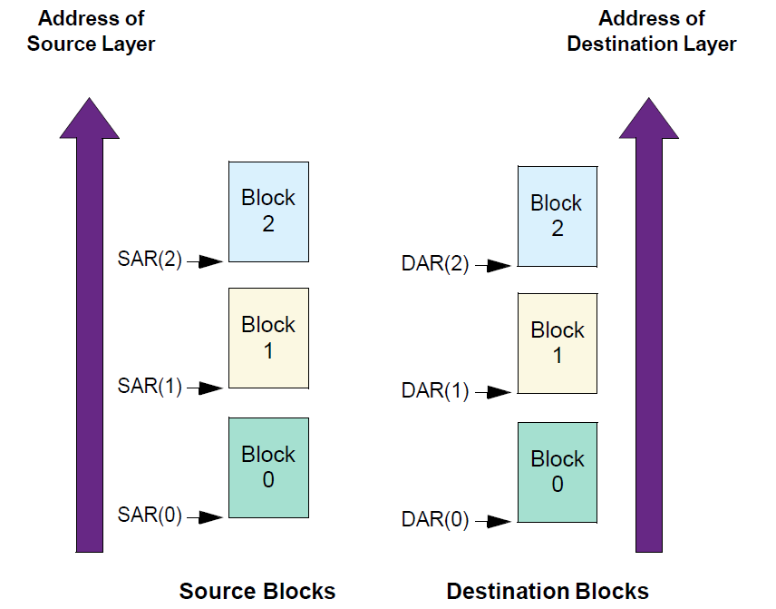
For multi-block transfers, the SAR and DAR register can be auto-reloaded from its initial value at the end of each block, as shown in Multi-block DMA transfer with source and destination address auto-reloaded.. |
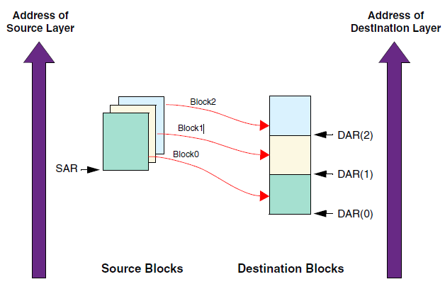
Multi-block DMA transfer with source address auto-reloaded and contiguous destination address.
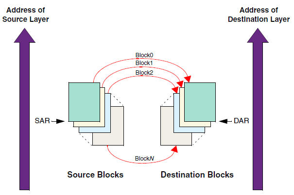
Multi-block DMA transfer with source and destination address auto-reloaded.
Linked list Mode
In linked list mode, the addresses between data blocks do not have to be consecutive.
Link list transfer types |
Setting |
Introduction |
|---|---|---|
Src: Continue address Dst: Link list |
PGDMA_InitTypeDef->GDMA_SrcAddr = pSrc PGDMA_InitTypeDef->GDMA_LlpDstEn = 1 |
Source memory is a continuous data block, while destination data blocks are organized in linked list. |
Src: Auto-reloading Dst: Link list |
PGDMA_InitTypeDef->GDMA_ReloadSrc = 1 PGDMA_InitTypeDef->GDMA_SrcAddr = pSrc PGDMA_InitTypeDef->GDMA_LlpDstEn = 1 |
In source, SAR register can be auto-reloaded from the initial value at the end of each block, as shown in Multi-block DMA transfer with source address auto-reloaded and linked list destination address. |
Src: Link list Dst: Continue address |
PGDMA_InitTypeDef->GDMA_LlpSrcEn = 1 PGDMA_InitTypeDef->GDMA_DstAddr = pDst |
Source memory is organized in the form of a linked list, and destination memory is a continuous data block, as shown in Multi-block DMA transfer with linked list source address and contiguous destination address. |
Src: Link list Dst: Auto-reloading |
PGDMA_InitTypeDef->GDMA_LlpSrcEn = 1 PGDMA_InitTypeDef->GDMA_DstAddr = pDst PGDMA_InitTypeDef->GDMA_ReloadDst = 1 |
The source data blocks are organized in a linked list, and the destination data blocks are auto-reloading. |
Src: Link list Dst: Link list |
PGDMA_InitTypeDef->GDMA_LlpSrcEn = 1 PGDMA_InitTypeDef->GDMA_LlpDstEn = 1 |
Both source and destination data blocks are organized in linked lists, as shown in Multi-block DMA transfer with linked address for source and destination. |
If both the destination and the source are continuous data blocks, multi-block transmission should not be used, and single-block transmission is more appropriate.
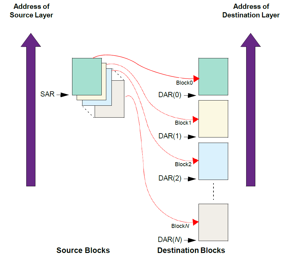
Multi-block DMA transfer with source address auto-reloaded and linked list destination address
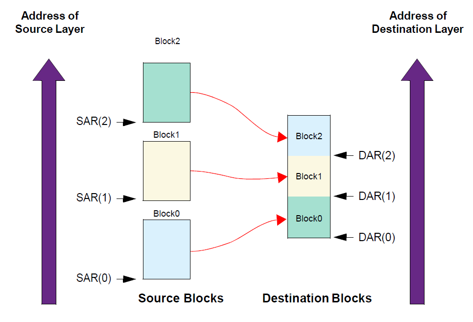
Multi-block DMA transfer with linked list source address and contiguous destination address
Multi-block DMA transfer with linked address for source and destination
Address Increment Type
Source Address Increment
There are two modes:
Increment: Indicates whether to increment the source address on every source transfer. Incrementing is done for alignment to the next CTLx.SRC_TR_WIDTH boundary.
No change: If the device is fetching data from a source peripheral FIFO with a fixed address, then set this field to No change.
Destination Address Increment
There are two modes:
Increment: indicates whether to increment destination address on every destination transfer. Incrementing is done for alignment to the next CTLx.DST_TR_WIDTH boundary.
No change: If the device is writing data to a destination peripheral FIFO with a fixed address, then set this field to No change.
Configuration Principles:
If the source or destination is Memory, the address mode is generally set to Increment.
If the source or destination is a Peripheral, the address mode is generally set to No Change.
FIFO
Each GDMA channel has its own independent FIFO, and the FIFO sizes of different channels are not the same.
Channel Number |
CH0 |
CH1 |
CH2~CH7 |
|---|---|---|---|
FIFO size/Bytes |
128 |
128 |
32 |
Interrupt Type
There are several supported interrupt types, which can be used independently or in combination.
Interrupt type |
Introduction |
|---|---|
block interrupt |
Triggered by the completion of a data block transfer |
transfer interrupt |
Occurs when all data blocks have been transferred |
error interrupt |
There was a transfer error |
Note
In multi-block, when the block in auto-reload mode is interrupted, the data will be transmitted after the interrupt processing function.
In linked list mode, the transfer-completed condition is that the pointer of the last data block pointing to the next data block is null.
In linked list mode, when the block interruption comes, the data will still continue to be transmitted.
Suspend and Abort
GDMA supports channel suspend resume and termination.
To suspend a channel, just configure CFGx.CH_SUSP, but there is no guarantee that the current data transaction is completed. Combined with CFGx.INACTIVE, the channel can be safely paused without losing data.
To resume data transmission after suspension, clear CFGx.CH_SUSP.
To terminate data transfer, CFGx.INACTIVE must be continuously polled until this bit is set to 1, then the data transfer can be aborted.
Note
The following is situation that channels is inactive:
CFGx.INACTIVEcan only be activated after Memory has been written, and then canceled.The data of peripheral is 4 bytes, but the FIFO of DMAC is only 2 bytes. There is no writing at this time and
CFGx.INACTIVEis activated directly.
Gather and Scatter
Gather
A gather transfer copies multiple segments of data, spaced at regular intervals within a source memory region, into a contiguous area in the destination memory. The example below demonstrates this:
SRC_TR_WIDTHis 4 BytesSource Gather Interval (SGI)is 1Source Gather Count (SGC)is 4
This means that for each transfer, the source reads 16Bytes of data, then skips an address range of 4Bytes before the next read. Eventually, the gathered data is stored contiguously in the destination memory.

Scatter
A scatter transfer copies data from a contiguous source memory region into a non-contiguous (periodically spaced) region in the destination memory. The example below demonstrates this:
DST_TR_WIDTHis 4 BytesDestination Scatter Interval (DSI)is 16Destination Scatter Count (DSC)is 4
This means the source sends data continuously, while the destination writes 16Bytes of data at a time and then skips 64Bytes before the next write.

Warning
When using the Source Gather function to collect memory data from the source into the destination, block_ts must match the amount of valid data to be transferred and must be aligned with
SRC_TR_WIDTH.When using the Destination Scatter function to scatter data from the source to the destination, block ts must match the size of the source address space and must be aligned with
DST_TR_WIDTH.
Priority
GDMA supports two kinds of channel priority:
Software: the priority of each channel can be configured in the
CFGx.CH_PRIOR. The valid value is 0 ~ (DMAC_NUM_CHANNELS-1), where 0 is the highest priority value and (DMAC_NUM_CHANNELS-1) is the lowest priority value.Hardware: if two channel requests have the same software priority level, or if no software priority is configured, the channel with the lower number takes priority over the channel with the higher number. For example, channel 2 takes priority over channel 4.
Handshake
GDMA supports only hardware handshake and does not support software handshake. The handshake interface needs to be configured only when transferring data between GDMA and peripherals. All hardware handshake interfaces are fixed during IC design and cannot be modified by users. The hardware handshake interfaces supported by the current IC and their corresponding IPs are listed in the following table:
Function |
Handshake Number |
Comment |
|---|---|---|
UART0 TX |
0 |
|
UART0 RX |
1 |
|
UART1 TX |
2 |
|
UART1 RX |
3 |
|
UART2 TX |
4 |
|
UART2 RX |
5 |
|
SPI0 TX |
6 |
|
SPI0 RX |
7 |
|
SPI1 TX |
8 |
|
SPI1 RX |
9 |
|
SPIC TX |
10 |
|
SPIC RX |
11 |
|
SPORT0 TX |
12 |
Two FIFOs, occupies 12 & 13 |
SPORT0 RX |
14 |
Two FIFOs, occupies 14 & 15 |
SPORT1 TX |
16 |
Two FIFOs, occupies 16 & 17 |
SPORT1 RX |
18 |
Two FIFOs, occupies 18 & 19 |
LEDC_TX |
20 |
|
I2C0 TX |
21 |
|
I2C0 RX |
22 |
|
I2C1 TX |
23 |
|
I2C1 RX |
24 |
Function |
Handshake No. |
Description |
|---|---|---|
UART0 TX |
0 |
|
UART0 RX |
1 |
|
UART1 TX |
2 |
|
UART1 RX |
3 |
|
UART2 TX |
4 |
|
UART2 RX |
5 |
|
UART3 TX |
6 |
|
UART3 RX |
7 |
|
SPI0 TX |
8 |
|
SPI0 RX |
9 |
|
SPI1 TX |
10 |
|
SPI1 RX |
11 |
|
SPIC TX |
12 |
|
SPIC RX |
13 |
|
SPORT0 TX |
14 |
Two FIFOs, occupies No. 14 and 15 |
SPORT0 RX |
16 |
Two FIFOs, occupies No. 16 and 17 |
SPORT1 TX |
18 |
Two FIFOs, occupies No. 18 and 19 |
SPORT1 RX |
20 |
Two FIFOs, occupies No. 20 and 21 |
LEDC_TX |
22 |
|
Zigbee_TX |
23 |
|
Zigbee_RX |
24 |
Function |
Handshake No. | Description |
|
|---|---|---|
UART0 TX |
0 |
|
UART0 RX |
1 |
|
UART1 TX |
2 |
|
UART1 RX |
3 |
|
UART2 TX |
4 |
|
UART2 RX |
5 |
|
SPI0 TX |
6 |
|
SPI0 RX |
7 |
|
SPI1 TX |
8 |
|
SPI1 RX |
9 |
|
QSPI |
10 |
|
SPIC TX |
11 |
|
SPIC RX |
12 |
|
SPORT0 TX |
13 |
Two FIFOs, occupies 13 & 14 |
SPORT0 RX |
15 |
Two FIFOs, occupies 15 & 16 |
SPORT1 TX |
17 |
Two FIFOs, occupies 17 & 18 |
SPORT1 RX |
19 |
Two FIFOs, occupies 19 & 20 |
SPORT2 TX |
21 |
Two FIFOs, occupies 21 & 22 |
SPORT2 RX |
23 |
Two FIFOs, occupies 23 & 24 |
SPORT3 TX |
25 |
Two FIFOs, occupies 25 & 26 |
SPORT3 RX |
27 |
Two FIFOs, occupies 27 & 28 |
LEDC_TX |
29 |
|
Zigbee_TX |
30 |
|
Zigbee_RX |
31 |
|
UART3_TX |
32 |
|
UART3_RX |
33 |
|
Function |
Handshake Number |
Comment |
|---|---|---|
UART0 TX |
0 |
|
UART0 RX |
1 |
|
UART1 TX |
2 |
|
UART1 RX |
3 |
|
UART2 TX |
4 |
|
UART2 RX |
5 |
|
SPI0 TX |
6 |
|
SPI0 RX |
7 |
|
SPI1 TX |
8 |
|
SPI1 RX |
9 |
|
SPIC TX |
10 |
|
SPIC RX |
11 |
|
SPORT0 TX |
12 |
|
SPORT0 RX |
13 |
|
SPORT1 TX |
14 |
|
SPORT1 RX |
15 |
|
I2C0 TX |
16 |
|
I2C0 RX |
17 |
|
I2C1 TX |
18 |
|
I2C1 RX |
19 |
|
CAN0_RX |
20 |
|
CAN1_RX |
21 |
|
UART_LOG_RX |
22 |
|
UART_LOG_TX |
23 |
|
UART3_TX |
24 |
|
UART3_RX |
25 |
|
PSRAMC_RX |
26 |
|
CTC_RX |
27 |
Real-time Status Acquisition
GDMA supports real-time acquisition of the current transmission source address, destination address and the data size that has been transmitted. Call the corresponding APIs to read.
Note
To get the amount of data that has been transferred, the block_ts must be greater than 768 at least, and cannot be read in an interrupt function; otherwise, the value obtained is always 0.
Security Mechanism
By default, the secure transfer feature of GDMA is disabled. When users need to use this feature, they must first enable the Trustzone feature.
GDMA supports independent configuration of the secure transfer feature for each channel. Once this feature is enabled, the DMAC will initiate secure access requests through the AXI master interface. At this point, GDMA can transfer data between secure and non-secure peripherals (or memory).
Secure channels can only be configured within the secure world, and secure channels can access both secure peripherals (memory) and non-secure peripherals (memory).
Non-secure channels can only access non-secure peripherals (memory).
To enable the secure transfer feature for a specific channel, set the following structure member when configuring GDMA parameters in Secure code:
PGDMA_InitTypeDef->SecureTransfer = 1;
DMA and Cache
When using DMA to transfer data between memory regions or between memory and peripherals, if the cache is also enabled, attention must be paid to the problem of cache and memory data inconsistency.
DMA TX
When the DMA source is memory and you need to send data, the general process is as follows:
Allocate a transmission buffer, ensuring that the starting address and size are aligned with the cache line.
The CPU writes data into the memory buffer.
Call the
Dcache_Clean()function to clean the data cache.Configure DMA transmission parameters.
Start DMA transfer.
DMA RX
The CPU allocates a receive buffer.
Execute
DCache_Clean()to ensure the receive buffer is in a clean state (if the receive buffer is already clean, this step can be skipped).Caution
The reason for this step is:
For Cortex-A32, if the receive buffer in the cache is in a dirty state, executing step 5
DCache_Invalidate()will perform both clean and invalidate operations, which may lead to unexpected write actions.If the receive buffer in the cache is dirty, when the CPU’s D-Cache is full, the CPU may write back dirty data in the receive buffer to memory, overwriting the content already written by DMA.
Configure DMA Rx parameters.
Handle DMA Rx interrupt.
Execute
DCache_Invalidate()to invalidate cache data and ensure that there is no residual old data from the receive buffer in the cache.
Caution
This step must be performed for the following reasons:
For CPUs with automatic data prefetch (such as Cortex-A32 and DSP), when the CPU reads addresses adjacent to the receive buffer, the CPU will perform a line fill operation in the background and automatically reload the old value of the receive buffer into the cache.
This prevents the CPU from reading old values into the cache during DMA processing.
The CPU reads the receive buffer (the value returned by DMA Rx).
Note
Aligning the buffer address with the cache line will reduce the problem of inconsistent cache and memory data.
DMAC Demos
Single Block
Allocate a free channel
ch_num = GDMA_ChnlAlloc(gdma.index, (IRQ_FUN) Dma_memcpy_int, (u32)(&gdma), 3);
This function also includes the following operation:
Register IRQ handler if using interrupt mode
Enable NVIC interrupt
Register the GDMA channel to use
Configure the interrupt type
PGDMA_InitTypeDef->GDMA_IsrType = (TransferType | ErrType);
Configure interrupt handling function
Clear the pending interrupt in the interrupt processing function.
GDMA_ClearINT(0, PGDMA_InitTypeDef->GDMA_ChNum);
Configure transfer settings
PGDMA_InitTypeDef->GDMA_SrcMsize   = MsizeEight;
PGDMA_InitTypeDef->GDMA_SrcDataWidth = TrWidthFourBytes;
PGDMA_InitTypeDef->GDMA_DstMsize = MsizeEight;
PGDMA_InitTypeDef->GDMA_DstDataWidth = TrWidthFourBytes;
PGDMA_InitTypeDef->GDMA_BlockSize = DMA_CPY_LEN >> 2;
PGDMA_InitTypeDef->GDMA_DstInc = IncType; // if dst type is peripheral:no change
PGDMA_InitTypeDef->GDMA_SrcInc = IncType; // if src type is peripheral:no change
Configure hardware handshake interface if slave is peripheral
GDMA_InitStruct->GDMA_SrcHandshakeInterface= GDMA_HANDSHAKE_INTERFACE_AUDIO_RX;
or
GDMA_InitStruct->GDMA_DstHandshakeInterface = GDMA_HANDSHAKE_INTERFACE_AUDIO_TX;
Configure the transfer address
PGDMA_InitTypeDef->GDMA_SrcAddr = (u32)BDSrcTest;
PGDMA_InitTypeDef->GDMA_DstAddr = (u32)BDDstTest;
Program GDMA index, GDMA channel, data width, msize, transfer direction, address increment mode, hardware handshake interface, reload control, interrupt type, block size, multi-block configuration and the source and destination address using the
GDMA_Init()function.GDMA_Init(gdma.index, gdma.ch_num, PGDMA_InitTypeDef);
Clean and invalidate Cache
DCache_CleanInvalidate();
Enable GDMA channel
GDMA_Cmd(gdma.index, gdma.ch_num, ENABLE);
Multi-block
This example is SRC auto reload, compared with single block, multi-block is different in Step 2 to Step 4.
Allocate a free channel
ch_num = GDMA_ChnlAlloc(gdma.index, (IRQ_FUN) Dma_memcpy_int, (u32)(&gdma), 3);
This function also includes the following operation:
Register IRQ handler if use interrupt mode
Enable NVIC interrupt
Register the GDMA channel to use
Configure the interrupt type
PGDMA_InitTypeDef->GDMA_IsrType = (BlockType | TransferType | ErrType);
Configure interrupt handling function
Clear the interrupt.
GDMA_ClearINT(0, GDMA_InitStruct->GDMA_ChNum);
Clear the auto reload mode before the last block starts.
GDMA_ChCleanAutoReload(0, GDMA_InitStruct->GDMA_ChNum, CLEAN_RELOAD_SRC);
Configure transfer settings
PGDMA_InitTypeDef->GDMA_SrcMsize   = MsizeEight;
PGDMA_InitTypeDef->GDMA_SrcDataWidth = TrWidthFourBytes;
PGDMA_InitTypeDef->GDMA_DstMsize = MsizeEight;
PGDMA_InitTypeDef->GDMA_DstDataWidth = TrWidthFourBytes;
PGDMA_InitTypeDef->GDMA_BlockSize = DMA_CPY_LEN >> 2;
PGDMA_InitTypeDef->GDMA_DstInc = IncType; // If DST type is peripheral: no change
PGDMA_InitTypeDef->GDMA_SrcInc = IncType; // If SRC type is peripheral: no change
PGDMA_InitTypeDef->GDMA_ReloadSrc = 1;
PGDMA_InitTypeDef->GDMA_ReloadDst = 0;
Configure hardware handshake interface if slave is peripheral.
GDMA_InitStruct->GDMA_SrcHandshakeInterface= GDMA_HANDSHAKE_INTERFACE_AUDIO_RX;
or
GDMA_InitStruct->GDMA_DstHandshakeInterface = GDMA_HANDSHAKE_INTERFACE_AUDIO_TX;
Configure the transfer address
PGDMA_InitTypeDef->GDMA_SrcAddr = (u32)BDSrcTest;
PGDMA_InitTypeDef->GDMA_DstAddr = (u32)BDDstTest;
Program GDMA index, GDMA channel, data width, Msize, transfer direction, address increment mode, hardware handshake interface, reload control, interrupt type, block size, multi-block configuration and the source and destination address using the
GDMA_Init()function.GDMA_Init(gdma.index, gdma.ch_num, PGDMA_InitTypeDef);
Clean and invalidate Cache
DCache_CleanInvalidate();
Enable GDMA channel
GDMA_Cmd(gdma.index, gdma.ch_num, ENABLE);