Zephyr 快速指南
DTS 快速指南
DTS 详细介绍请参考 Zephyr 配置系统
DTS 语法和使用简介
修改 DTS 配置
Zephyr 中 DTS 是分散在多个文件中的, 详见 unit-address, 修改 DTS 时修改哪个文件要视情况而定
到对应 test/sample 源码目录下(test 通常是
zephyr/tests/*/boards, sample 通常是zephyr/samples/*/boards)新增(如果没有)对应 board 的 overlay 文件并进行修改如下 overlay 例子是增加一个 led 节点, 设置相关 gpio 口, 并为该节点取别名
led0:
/ {
  aliases {
    led0 = &led_0;
  };

  gpio-led {
    compatible = "gpio-leds";
    led_0: led_0 {
      gpios = <&gpioa 25 0>;
    };
  };
};
如下例子是修改已有 DTS 中的配置(将
status改为okay)
&gpioa {
  status = "okay";
};
在对应 board 级 dts 目录新增 overlay 文件, 文件命名规则:
<origin_board_dts_basename>_<revision>.overlay, 其中revision支持多种形式修改同目录下的
revision.cmake(如果没有则创建), 通过DEFAULT_REVISION参数指定对应 overlay 文件
board_check_revision(
    FORMAT_LETTER
    DEFAULT_REVISION D  # <revision> is D
)

board_check_revision(
    FORMAT_MAJOR.MINOR.PATH
    DEFAULT_REVISION 2.0.0  # <revision> is 2.0.0
)

board_check_revision(
    FORMAT_NUMBER
    DEFAULT_REVISION 2  # <revision> is 2
)
如何确认 DTS 最终配置是否正确
Zephyr DTS 因为涉及多个文件, 同一个配置项可能会被多处设置或重置, 所以直接看某个文件不能反映最终的结果, 如:
检查修改(overlay)是否生效
检查某个设备的状态(
okay或disable)或属性设置是否符合预期
此时可以查看 build/zephyr/zephyr.dts 文件, 它是最终生成的 DTS 文件
如何查看某个设备的 binding 文件
binding 文件介绍请参考 DTS binding
到定义设备的 dts 中找到其 compatible 字段, 如:
compatible = "realtek,ameba-rcc";查找名为
realtek,ameba-rcc.ymal文件, 确认其中compatible值为"realtek,ameba-rcc", 则该文件为对应 binding 文件
注意
这种方法只有 binding 文件命名遵循了与 compatible 字段相同的规则才可以使用这种方法, 但这种规则在 zephyr 中不是强制的, 若不一致需要通过方法 2
定位到
devicetree_generated.h文件, 在文件开头位置找到所需设备完整节点名称, 如/soc/gpio@41010000
* Node dependency ordering (ordinal and path):
*   0   /
*   1   /aliases
*   2   /chosen
*   3   /soc
*   4   /soc/interrupt-controller@e000e100
*   5   /soc/gpio@41010000
*   6   /buttons
*   7   /buttons/button_0
*   8   /clocks
*   9   /clocks/clk_sys
*   10  /cpus
继续在文件中检索
Devicetree node: /soc/gpio@41010000, 找到如下位置:
/*
* Devicetree node: /soc/gpio@41010000
*
* Node identifier: DT_N_S_soc_S_gpio_41010000
*
* Binding (compatible = realtek,ameba-gpio):
*   $ZEPHYR_BASE/dts/bindings/gpio/realtek,ameba-gpio.yaml
*
* (Descriptions have moved to the Devicetree Bindings Index
* in the documentation.)
*/
第 7 行就是该设备所用的 binding 文件的完整路径
在代码中如何访问 DTS
访问 DTS 通常是为了获取某个节点的属性或者驱动, 可以参照如下步骤:
假如有 DTS 内容如下:
/ {
    soc {
        serial0: serial@40002000 {
            reg = <0x4000200 0x100>
            status = "okay";
            current-speed = <115200>;
            /* ... */
        };
    };

    aliases {
        my-serial = &serial0;
    };

    chosen {
        zephyr,console = &serial0;
    };
};
首先获取某个节点标志符. DTS 中有多种方法标志一个节点, 所以也对用多种方法获取节点:
/* Option 1: by node label */
#define MY_SERIAL DT_NODELABEL(serial0)

/* Option 2: by alias */
#define MY_SERIAL DT_ALIAS(my_serial)

/* Option 3: by chosen node */
#define MY_SERIAL DT_CHOSEN(zephyr_console)

/* Option 4: by path */
#define MY_SERIAL DT_PATH(soc, serial_40002000)
上述代码中宏
MY_SERIAL即表示节点标识符, 利用它可以进一步得到节点属性或驱动
/* Demo 1: conditional compilation based on node status */
#if DT_NODE_HAS_STATUS(MY_SERIAL, okay)
//Desired code when node is okay(enabled)
#endif

/* Demo 2: get normal property */
u32 speed = DT_REG_ADDR(MY_SERIAL);  //=0x4000200

/* NOTE: some property have exclusive macro */
/* Demo 3: get reg info */
u32 addr = DT_REG_ADDR(MY_SERIAL);  //=0x4000200
u32 size = DT_REG_SIZE(MY_SERIAL);  //=0x100
const struct device *const dev = DEVICE_DT_GET(MY_SERIAL);

if (!device_is_ready(dev)) {
    /* Not ready, do not use */
    return -ENODEV;
}
uart_poll_out(dev, 'a');
更多进阶用法参考 扩展阅读
在 Kconfig 中如何访问 DTS
参考: Kconfig 快速指南
在 CMake 中如何访问 DTS
参考: CMake 快速指南
如何定位 undefined reference 的 DTS 符号问题
DTS 中的定义的节点会在驱动代码中被定义为某个符号, 其标识符是按照某些编码规范生成, 如
__device_dts_ord_22实际使用中可能会遇到类似如下的编译错误:
/opt/rtk-toolchain/asdk-12.3.1-4431/linux/newlib/bin/../lib/gcc/arm-none-eabi/12.3.1/../../../../arm-none-eabi/bin/ld.bfd: app/libapp.a(test_counter.c.obj):(.rodata.devices+0x0): undefined reference to `__device_dts_ord_22'
出现该问题的原因通常是驱动层之上的代码引用了一个符号(驱动实例), 但链接时没有找到该驱动实例的符号定义(代码实现)
这里无法直接通过名字
__device_dts_ord_22定位到相关的代码区域, 下面给出一个针对上述错误的排查流程
首先定位出问题的 DTS 节点: 通过
test_counter.c.obj可以确定引用该符号的源文件是test_counter.c, 此时可以选择直接查看该文件, 分如下两种情况:如果只有一个驱动实例引用, 就可以通过代码确定对应的 DTS 节点信息(节点名称, label 等), 例如可能有如下代码:
#define I2C_DEV_NODE DT_ALIAS(i2c_0)
const struct device *const i2c_dev = DEVICE_DT_GET(I2C_DEV_NODE);
此时可以很容易判断是
i2c_0这个 DTS 节点对应设备的驱动定义有问题如果代码复杂, 有多个驱动实例引用或复杂的预处理逻辑, 则可以通过生成预处理文件直接精确定位 DTS 节点, 步骤如下
在文件
build/compile_commands.json中查找test_counter.c.obj, 可以定位到如下一个位置(表示部分省略 xxx 内容):{ "directory": "/xxx/build", "command": "/xxx/arm-none-eabi-gcc xxx -o CMakeFiles/app.dir/src/test_counter.c.obj -c /xxx/zephyr/tests/drivers/counter/counter_basic_api/src/test_counter.c", "file": "/xxx/zephyr/tests/drivers/counter/counter_basic_api/src/test_counter.c", "output": "CMakeFiles/app.dir/src/test_counter.c.obj" },
其中
command字段是编译test_counter.c的完整命令, 需要对完整的该命令稍作修改:-o输出路径,-c改为-E,然后在终端执行:/xxx/arm-none-eabi-gcc xxx -o test_counter.i -E /xxx/zephyr/tests/drivers/counter/counter_basic_api/src/test_counter.c",
此时会在执行目录生成一个文件
test_counter.i, 打开该文件搜索未定义符号__device_dts_ord_22可以找到如下内容:static const struct device *const devices[] = { # 63 "/xxx/zephyr/tests/drivers/counter/counter_basic_api/src/test_counter.c" # 124 "/xxx/zephyr/tests/drivers/counter/counter_basic_api/src/test_counter.c" (&__device_dts_ord_22), (&__device_dts_ord_23), (&__device_dts_ord_24), (&__device_dts_ord_25), # 144 "/xxx/zephyr/tests/drivers/counter/counter_basic_api/src/test_counter.c" };
通过上述第 4, 5 行可知
__device_dts_ord_22是在源文件 124 行引用的, 定位到该行代码如下:#ifdef CONFIG_COUNTER_TMR_AMEBA DEVS_FOR_DT_COMPAT(realtek_ameba_counter) #endif
由此可知是
compatiable为realtek,ameba-counter的 DTS 节点对应设备的驱动定义有问题
排查 DTS 节点对应的驱动定义问题, 可以参考以下思路:
DTS 节点不存在或未使能(
status未设置为okay), 可以参考 如何确认 DTS 最终配置是否正确DTS 节点对应驱动代码未加入编译, 这里要检查相关驱动的
CMakeLists.txt或 Kconfig 配置DTS 节点驱动代码中编码问题, 例如
DT_DRV_COMPAT宏定义是否正确等
Kconfig 快速指南
Kconfig 中获取 DTS 中的信息
Zephyr 提供了系列接口支持在 Kconfig 中访问 DTS 中的信息: Devicetree-related Functions.
如下是一些使用示例:
config AMEBA_PSRAM
  def_bool y if $(dt_nodelabel_enabled,psram)  # init bool value by node state

config AMEBA_PSRAM_SIZE
  hex
  depends on AMEBA_PSRAM
  default $(dt_nodelabel_reg_size_hex,psram)  # init hex value by node reg's size cell
对应 DTS:
psram: memory@60000000 {
  compatible = "zephyr,memory-region";
  device_type = "memory";
  reg = <0x60000000 DT_SIZE_M(4)>;
  zephyr,memory-region = "PSRAM";
  status = "disabled";
};
CMake 快速指南
CMake 中获取 DTS 中的信息
Zephyr 提供了系列接口支持在 CMake 中访问 DTS 中的信息, 其函数实现可以参考: zephyr/cmake/modules/extensions.cmake
如下是一些 api 说明:
API |
Description |
|---|---|
|
Function for retrieving the node path for the node having nodelabel |
|
Get a node path for an /aliases node property |
|
Tests whether a node with path <path> exists in the devicetree |
|
Tests whether <path> refers to a node which exists in the devicetree, and has a status property matching the <status> argument |
|
Get a devicetree property value. The value will be returned in the <var> parameter |
|
Get a list of paths for the nodes with the given compatible. The value will be returned in the <var> parameter |
|
Get the number of register blocks in the node's reg property |
|
Get the base address of the register block at index <idx>, or with name <name> |
|
Get the size of the register block at index <idx>, or with name <name> |
|
Test if the devicetree's /chosen node has a given property <prop> which contains the path to a node |
|
Get a node path for a /chosen node property |
NVIC 快速指南
NVIC 详细介绍请参考 NVIC 介绍
zephyr 中断使用说明
在 Zephyr 中开发驱动使用中断需要完成几个关键步骤,即可正常响应中断。
下面将给出一个使用示例,并列举其中的关键步骤。
代码示例
DTS 配置:
中断设备树配置示例1nvic: interrupt-controller@e000e100 { 2 #address-cells = < 0x1 >; 3 compatible = "arm,v8.1m-nvic"; 4 reg = < 0xe000e100 0xc00 >; 5 interrupt-controller; 6 #interrupt-cells = < 0x2 >; 7 arm,num-irq-priority-bits = < 0x3 >; 8 phandle = < 0x1 >; 9}; 10timer0: counter@40819000 { 11 compatible = "realtek,ameba-counter"; 12 reg = <0x40819000 0x30>; 13 clocks = <&rcc AMEBA_LTIM0_CLK>; 14 interrupts = <7 0>; 15 clock-frequency = <32768>; 16 status = "disabled"; 17};
C 代码实现:
中断驱动代码实现示例1#define DT_DRV_COMPAT realtek_ameba_counter 2... 3 4void counter_ameba_isr(const struct device *dev) 5{ 6} 7 8#define TIMER_IRQ_CONFIG(n) \ 9 static void irq_config_##n(const struct device *dev) \ 10 { \ 11 IRQ_CONNECT(DT_INST_IRQN(n), DT_INST_IRQ(n, priority), counter_ameba_isr, \ 12 DEVICE_DT_INST_GET(n), 0); \ 13 irq_enable(DT_INST_IRQN(n)); \ 14 } 15 16#define AMEBA_COUNTER_INIT(n) \ 17 TIMER_IRQ_CONFIG(n) \ 18 ... 19 20DT_INST_FOREACH_STATUS_OKAY(AMEBA_COUNTER_INIT);
关键步骤
确认硬件支持, DTS 中配置中断信息。
如上 中断设备树配置示例 中高亮行 14 行所示设置驱动的中断属性,
interrupts有两个入参,第一个是中断号,第二个是中断优先级。驱动代码中实现中断服务函数,注册中断时需要用到,如上 中断驱动代码实现示例 4-6 行。
驱动代码中从 DTS 获取中断优先级等属性,注册中断时需要用到,如上 中断驱动代码实现示例 11 行。 详细介绍请参考 获取中断属性。
/*获取中断号*/
DT_INST_IRQN(n);
/*获取中断优先级*/
DT_INST_IRQ(n, priority);
驱动代码中注册中断,如上 中断驱动代码实现示例 11 行。 详细介绍请参考 中断注册。
驱动代码中启用中断,如上 中断驱动代码实现示例 13 行。 详细介绍请参考 启用/关闭中断。
文件系统 快速指南
文件系统详细介绍参考 文件系统 介绍
LitteFS on FLASH
样例路径: zephyr/samples/subsys/fs/littlefs/
使用以下命令编译 LitteFS on FLASH 样例:
./nuwa.py build -a zephyr/samples/subsys/fs/littlefs/ -d rtl8721f_evb
当需要自定义 DTS 时,可参考 LittleFS on FLASH 样例 配置。
可通过最终生成的 DTS 文件 build/zephyr/zephyr.dts 进一步检查 DTS 配置的正确性:
spic 的 status = "okay"
LitteFS 使用的 partition 起始地址和大小符合预期
如果遇到链接错误,可能是某些功能未使能。
可以通过 build/zephyr/include/generated/zephyr/autoconf.h 检查最终的 conf 配置。
LitteFS on FLASH 需要以下配置处于使能状态:
CONFIG_FILE_SYSTEM=y
CONFIG_FILE_SYSTEM_LITTLEFS=y
CONFIG_FLASH=y
CONFIG_FLASH_MAP=y
FatFS on SD
样例路径: zephyr/samples/subsys/fs/fs_sample/
使用以下命令编译 FatFS on SD 样例:
./nuwa.py build -a zephyr/samples/subsys/fs/fs_sample/ -d rtl8721f_evb
如果遇到链接错误,可能是某些功能未使能。
可以通过 build/zephyr/include/generated/zephyr/autoconf.h 检查最终的 conf 配置。
FatFS on SD 需要以下配置处于使能状态:
CONFIG_FILE_SYSTEM=y
CONFIG_FAT_FILESYSTEM_ELM=y
CONFIG_DISK_ACCESS=y
CONFIG_DISK_DRIVERS=y
Settings 快速指南
Settings 详细介绍参考 Settings 介绍
样例路径: zephyr/samples/subsys/settings/
使用以下命令编译 Settings 样例:
./nuwa.py build -a zephyr/samples/subsys/settings/ -d rtl8721f_evb
可参考 settings 配置 配置 DTS。
DEBUG 快速指南
DEBUG 详细介绍请参考 DEBUG 介绍
debug 简介
DEBUG 包括两部分:
离线调试:不直接连接正在运行的目标。通过采集日志、coredump、跟踪数据、性能采样文件等离线数据,在本地或分析工具中复盘问题。
在线调试:调试工具直接连接到正在运行的目标系统(例如通过 JTAG/SWD、GDB 远程、网络/串口),在真实环境中进行断点、单步、变量查看与修改、寄存器/内存访问等操作。
离线调试
下面介绍一种分析 coredump 日志的离线调试方法。
配置
配置详细介绍可查看 coredump 配置
配置示例:
CONFIG_DEBUG_COREDUMP=y                 #启用 coredump 模块
CONFIG_DEBUG_COREDUMP_BACKEND_LOGGING=y #使用日志模块获取 coredump 输出
CONFIG_DEBUG_COREDUMP_MEMORY_DUMP_MIN=y #仅转储异常线程的堆栈、其线程结构以及一些其他最基本的必要数据
获取 coredump
转储内容详细介绍可查看 转储格式
根据已启用的后端,从设备获取 coredump 信息。比如启用的日志后端,可以通过日志工具保存打印的日志,获取日志文件 coredump.log。
解析
解析详细介绍可查看 解析步骤
使用日志后端解析 coredump 步骤如下:
运行 coredump 串行日志转换器,提取 coredump.log 中 coredump 部分数据,生成 coredump.bin :
./zephyr/scripts/coredump/coredump_serial_log_parser.py coredump.log coredump.bin
启动自定义 GDB 服务器,解析 zephyr.elf 和 coredump.bin,获取符号表和异常堆栈等信息,以供 gdb 调试器查询:
./zephyr/scripts/coredump/coredump_gdbserver.py build/zephyr/zephyr.elf coredump.bin
启动 GDB 调试器:
arm-none-eabi-gdb build/zephyr/zephyr.elf
在 GDB 内部,通过端口 1234 连接到 GDB 服务器:
(gdb) target remote localhost:1234
也可以从 GDB 内部启动 GDB 服务器:
启动 GDB :
arm-none-eabi-gdb build/zephyr/zephyr.elf
在 GDB 内部,使用以下选项启动 GDB 服务器
--pipe:(gdb) target remote | ./scripts/coredump/coredump_gdbserver.py --pipe build/zephyr/zephyr.elf coredump.bin
然后就可以使用 gdb 命令查看异常信息,比如:
检查 CPU 寄存器:
info registers查看回溯信息:
bt
在线调试
在线调试详细介绍可查看 在线调试
下面介绍使用 gdb 进行在线调试的方法,需要使用 Jlink 连接开发板和电脑,介绍三种典型场景。
使用 gdb 命令行调试的方式:
备注
PA18、PA19 不能被占用。
代码在 windows 电脑,开发板通过 jlink 与 windows 电脑连接,使用
west debug调试。直接在 windows 上使用west debug命令:west debug
输出如下:
PS D:\code\nuwa> west debug
-- west debug: rebuilding
ninja: no work to do.
-- west debug: using runner jlink
-- runners.jlink: reset after flashing requested
-- runners.jlink: JLink version: 8.40
-- runners.jlink: J-Link GDB server running on port 2335; no thread info available
GNU gdb (Realtek ASDK-12.3.1 Build 4431) 12.1.90.20221114-git
Copyright (C) 2022 Free Software Foundation, Inc.
License GPLv3+: GNU GPL version 3 or later <http://gnu.org/licenses/gpl.html>
This is free software: you are free to change and redistribute it.
There is NO WARRANTY, to the extent permitted by law.
Type "show copying" and "show warranty" for details.
This GDB was configured as "--host=x86_64-w64-mingw32 --target=arm-none-eabi".
Type "show configuration" for configuration details.
For bug reporting instructions, please see:
<https://www.gnu.org/software/gdb/bugs/>.
Find the GDB manual and other documentation resources online at:
    <http://www.gnu.org/software/gdb/documentation/>.

For help, type "help".
Type "apropos word" to search for commands related to "word"...
Reading symbols from D:\code\nuwa\build\zephyr\zephyr.elf...
Remote debugging using :2335
__enable_irq () at D:/code/nuwa/modules/hal/cmsis_6/CMSIS/Core/Include/cmsis_gcc.h:800
800       __ASM volatile ("cpsie i" : : : "memory");
Resetting target
(gdb)
代码在 linux 服务器,开发板通过 jlink 与 windows 电脑连接,使用 gdb 命令行工具调试。
在 windows 手动启动 JLinkGDBServer 连接开发板;
可以使用
sdk/amebagreen2_gcc_project/utils/jlink_script/ap_JLinkGDBServer.bat启动 JLinkGDBServer 脚本中已经有一些配置,可以直接连接 AP 核,双击脚本即可启动。在 linux 服务器启动 gdb 调试器连接 JLinkGDBServer。
~/code/nuwa$ arm-none-eabi-gdb
代码在 linux 服务器,开发板通过 jlink 与 windows 电脑连接,使用
west debug命令行调试。首先在 windows 上启动 JLinkRemoteServer;
直接双击 JLinkRemoteServer 软件启动,需要选择一个 port,用于监听 linux 服务器上 JLinkGDBServer 的连接。
在 linux 服务器上使用
west debug命令。west debug -i ip:port
备注
除了添加连接 AP 核调试的参数,还要添加一个
-i ip:port参数用于连接 windows 上的 JLinkRemoteServer
OTA 快速指南
OTA 详细介绍请参考 OTA 介绍。
环境准备与配置
1. PC 主机安装 MCUmgr 命令行工具
您可以从 Apache Mynewt 官网 下载对应平台的 newtmgr 工具包:
Windows 64-bit: apache-mynewt-newtmgr-bin-windows-1.14.0.tgz
Linux 64-bit: apache-mynewt-newtmgr-bin-linux-1.14.0.tgz
将解压后的 newtmgr 工具包路径添加至对应平台的环境变量中,
命令行执行 newtmgr --help,若显示全局选项即配置成功。
2. Zephyr 设备端的工程配置
示例路径: zephyr/samples/subsys/mgmt/mcumgr/smp_svr。
Flash 分区
smp_svr 示例采用的 Flash 分区布局,可参考 Flash 分区映射 配置。
基础 MCUboot 与 SMP 配置
您需要确保 smp_svr 示例的配置文件(如 prj.conf 或板卡特定的配置文件)中包含以下关键配置:
# 启用 MCUboot 引导程序
CONFIG_BOOTLOADER_MCUBOOT=y
CONFIG_UPDATEABLE_IMAGE_NUMBER=2                            # AP(固件 0) 和 NP(固件 1)
CONFIG_MCUMGR_GRP_IMG_ALLOW_CONFIRM_NON_ACTIVE_IMAGE_ANY=y  # 允许对非运行固件进行确认

# 使能 MCUmgr 必要的命令组
CONFIG_MCUMGR_GRP_IMG=y                                     # 固件管理命令组
CONFIG_MCUMGR_GRP_OS=y                                      # 基本 OS 命令组

# 启用 MCUmgr 和 SMP 服务
CONFIG_MCUMGR=y
CONFIG_MCUMGR_SMP_UART=y                                    # 使用 UART 作为传输层

# 配置 UART 缓冲区与 MTU(最大传输单元)
CONFIG_MCUMGR_TRANSPORT_NETBUF_SIZE=1024
CONFIG_UART_MCUMGR_RX_BUF_SIZE=256                          # 需要与 MCUmgr 工具设置的 MTU 匹配
您需要在应用程序的 sysbuild 配置文件 sysbuild.conf 中 指定升级方式,否则顶层会按默认逻辑选择 swap_using_move 方式。
# 配置升级方式
SB_CONFIG_MCUBOOT_MODE_SWAP_USING_OFFSET=y
UART 传输层配置
您需要在设备树(overlay 文件)中指定使用的 UART 引脚,并确保该 UART 端口已正确配置并启用。
/ {
   chosen {
      zephyr,uart-mcumgr = &uart2;
   };
};

&uart2 {
   pinctrl-0 = <&uart2_default>;
   pinctrl-names = "default";
   current-speed = <115200>;
   status = "okay";
};
编译命令
./nuwa.py build -d rtl8721f_evb//mcuboot -a zephyr/samples/subsys/mgmt/mcumgr/smp_svr --sysbuild -p
或者
west build -b rtl8721f_evb//mcuboot zephyr/samples/subsys/mgmt/mcumgr/smp_svr --sysbuild -p
设备上电/复位后,打开串口终端,确认示例已启动并打印初始化日志:
*** Booting Zephyr OS build f50378385a85 ***
<inf> smp_sample: build time: Jan  7 2026 11:52:35
OTA 升级操作流程
假设设备已运行包含 smp_svr 示例的固件,并且选定的 UART 端口已连接到 PC 。
建立 MCUmgr 连接
配置连接
命令格式: newtmgr conn add <连接名> type=<类型> connstring="<key=value[,key=value...]>"
示例:
$ newtmgr conn add myConn type=serial connstring=\"dev=<COM3>,baud=115200,mtu=256\"
Connection profile myConn successfully added
备注
波特率配置需要与设备树中的设定一致。MTU 配置需要与应用配置中的
CONFIG_UART_MCUMGR_RX_BUF_SIZE一致。newtmgr conn 配置其他传输方式,请参考 官网说明 。
查看固件列表
命令格式: newtmgr image list -c <connection_profile>
示例:
$ newtmgr image list -c myConn
Images:
image=0 slot=0
   version: 0.0.0
   bootable: true
   flags: active confirmed
   hash: d0d1fe6e6f39a65d2442009e6a620736ea88e437c7bd297abdd9e9eaf1e3e257
image=1 slot=0
   version: 0.0.0
   bootable: true
   flags: active confirmed
   hash: 8ea9150f95da9c3f97134984b731928ae93e14752c54fe53b629d005ab94a948
- 参数说明
- image:
多个固件时的固件编号 。
- slot:
槽位(0=主槽,1=次槽)
- version/hash:
版本号与哈希
- bootable:
该槽位是否存在有效固件(固件头部正确且可校验)
- flags:
active表示是正在运行的固件槽位pending表示在下次 reset 时 MCUboot 会测试该固件槽位confirmed表示该固件槽位已被确认,不会回滚
备注
编译新固件时,可修改版本号
CONFIG_MCUBOOT_IMGTOOL_SIGN_VERSION,方便版本管理和查询。当前 NP 固件总是使用与 AP 固件相同的版本号。
上传新固件
使用 image upload 命令将新编译好的、已签名的固件发送到设备。
命令格式: newtmgr image upload <image-file> -c <conn_profile> [-n <image_int>]
示例:
$ newtmgr -c myConn image upload -n 0 /path/to/your/image_0.bin
77.55 KiB / 77.55 KiB [=======================================================================] 100.00% 4.38 KiB/s 17s
Done

$ newtmgr -c myConn image upload -n 1 /path/to/your/image_1.bin
228.48 KiB / 228.48 KiB [=====================================================================] 100.00% 4.44 KiB/s 51s
Done
- 参数说明
- -n:
指定固件编号,缺省时表示固件 0 。
标记为待测试
传输成功后,新固件将存放在对应固件的次槽分区中。通过以下命令标记新固件为 test ,MCUboot 会在下次启动时尝试运行它。
命令格式: newtmgr -c <conn_profile> image test <hex-image-hash>
示例:
$ newtmgr -c myConn image test 99bb5f0867744a238693f522b31be146a74fca2ad587d878feebef70b7d1e812
Images:
image=0 slot=0
   version: 0.0.0
   bootable: true
   flags: active confirmed
   hash: d0d1fe6e6f39a65d2442009e6a620736ea88e437c7bd297abdd9e9eaf1e3e257
image=0 slot=1
   version: 0.0.1
   bootable: true
   flags: pending
   hash: 99bb5f0867744a238693f522b31be146a74fca2ad587d878feebef70b7d1e812
image=1 slot=0
   version: 0.0.0
   bootable: true
   flags: active confirmed
   hash: 8ea9150f95da9c3f97134984b731928ae93e14752c54fe53b629d005ab94a948
image=1 slot=1
   version: 0.0.1
   bootable: true
   flags:
   hash: 137d5f84dc5c302f2d15d22ca7fa76c48e030a5d5c6f73b6ae89598143af92fe
Split status: N/A (0)

$ newtmgr -c myConn image test 137d5f84dc5c302f2d15d22ca7fa76c48e030a5d5c6f73b6ae89598143af92fe
Images:
image=0 slot=0
   version: 0.0.0
   bootable: true
   flags: active confirmed
   hash: d0d1fe6e6f39a65d2442009e6a620736ea88e437c7bd297abdd9e9eaf1e3e257
image=0 slot=1
   version: 0.0.1
   bootable: true
   flags: pending
   hash: 99bb5f0867744a238693f522b31be146a74fca2ad587d878feebef70b7d1e812
image=1 slot=0
   version: 0.0.0
   bootable: true
   flags: active confirmed
   hash: 8ea9150f95da9c3f97134984b731928ae93e14752c54fe53b629d005ab94a948
image=1 slot=1
   version: 0.0.1
   bootable: true
   flags: pending
   hash: 137d5f84dc5c302f2d15d22ca7fa76c48e030a5d5c6f73b6ae89598143af92fe
Split status: N/A (0)
备注
被指定为测试的固件槽位信息中可以看到:
flags: pending。
重启设备
可以通过 MCUmgr 工具发送重启命令,或手动复位设备。
触发 reset 后,MCUboot 检测到次槽被标记为 test,根据配置的 OTA 升级方式, 决定是否执行主/次槽交换;采用 swap_using_xxx 策略时会在应用启动前完成交换。
命令格式: newtmgr reset -c <conn_profile>
示例:
$ newtmgr -c myConn reset
Done
确认新固件
设备重启并成功运行新固件后,必须执行确认操作,Zephyr 提供了两种确认方式:
应用程序自行确认
设备在启动并验证新固件成功后,由应用程序主动调用 MCUboot 提供的确认接口
boot_write_img_confirmed(),将当前固件标记为confirmed。通过 MCUmgr 工具下发确认命令
命令格式:
newtmgr image confirm [hex-image-hash] -c <conn_profile>示例:
$ newtmgr -c myConn image confirm 137d5f84dc5c302f2d15d22ca7fa76c48e030a5d5c6f73b6ae89598143af92fe
Images:
image=0 slot=0
   version: 0.0.1
   bootable: true
   flags: active confirmed
   hash: 99bb5f0867744a238693f522b31be146a74fca2ad587d878feebef70b7d1e812
image=1 slot=0
   version: 0.0.1
   bootable: true
   flags: active confirmed
   hash: 137d5f84dc5c302f2d15d22ca7fa76c48e030a5d5c6f73b6ae89598143af92fe
备注
被确认的固件槽位信息中可以看到:
flags: confirmed。当前 smp_svr 示例采用第二种确认方式。
MCUboot 快速指南
MCUboot 详细介绍请参考 MCUboot 介绍
编译 MCUboot 示例
基于 zephyr/samples/sysbuild/with_mcuboot,是一个最小示例,包含了最少且必要配置。
编译,执行命令:
./nuwa.py build -d rtl8721f_evb//mcuboot -a zephyr/samples/sysbuild/with_mcuboot --sysbuild -- -Dmcuboot_CONFIG_MCUBOOT_ACTION_HOOKS=y -DSB_CONFIG_MCUBOOT_MODE_SWAP_USING_OFFSET=y
固件下载
固件位于 sdk 根目录的 images 目录下
使用 Ameba Image Tool 下载时的配置参考下图
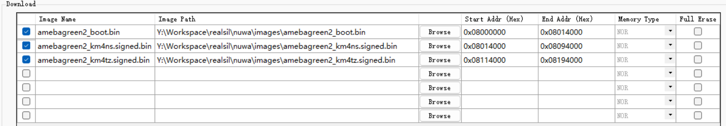
重新上电,看到如下日志可以确定
km4ns和km4tz两个 CPU 都成功运行19:16:56.145 [BOOT-I] ROM:[V1.0] 19:16:56.146 [BOOT-I] FLASH RATE:1, Pinmux:0 19:16:56.146 [BOOT-I] BOOT FROM NOR 19:16:56.146 [BOOT-I] Boot from Flash 19:16:56.146 [BOOT-I] IMG1(OTA1) Version: 1.1 19:16:56.147 [BOOT-I] IMG1 ENTRY [104032dd:0] 19:16:56.157 *** Booting MCUboot 116ced556cca *** 19:16:56.157 *** Using Zephyr OS build f998faa02fe0 *** 19:16:56.415 [BOOT-I] AP BOOT REASON 0: 19:16:56.416 Initial Power on 19:16:56.422 [CHIPINFO-E] Invalid BD number! 19:16:56.422 [CHIPINFO-I] MCM_TYPE_INVALID: BDnum1011 19:16:56.428 [APP-I] NP CPU CLK: 240000000 Hz 19:16:56.428 [CHIPINFO-E] Invalid BD number! 19:16:56.428 [CHIPINFO-I] MCM_TYPE_INVALID: BDnum1011 19:16:56.432 [MAIN-I] IWDG refresh thread Started! 19:16:56.435 [MAIN-I] NP OS START 19:16:56.507 [CLK-I] [CAL4M]: delta:2 target:320 PPM: 6250 PPM_Limit:30000 19:16:56.517 *** Booting Zephyr OS build f998faa02fe0 *** 19:16:56.517 Address of sample 0x4000000 19:16:56.517 Hello sysbuild with mcuboot! rtl8721f_evb
基于 zephyr/samples/subsys/mgmt/mcumgr/smp_svr,支持 SMP server 的更多功能,如 OTA。
编译,执行命令:
./nuwa.py build -d rtl8721f_evb//mcuboot -a zephyr/samples/subsys/mgmt/mcumgr/smp_svr --sysbuild -- -Dmcuboot_CONFIG_MCUBOOT_ACTION_HOOKS=y -DSB_CONFIG_MCUBOOT_MODE_SWAP_USING_OFFSET=y
固件下载,同示例一
重新上电,看到如下日志可以确定
km4ns和km4tz两个 CPU 都成功运行17:22:25.137 I: Image version: v0.0.0 17:22:25.137 I: Jumping to the first image slot 17:22:25.137 [BOOT-I] AP BOOT REASON 0: 17:22:25.137 Initial Power on 17:22:25.150 [CHIPINFO-E] Invalid BD number! 17:22:25.150 [CHIPINFO-I] MCM_TYPE_INVALID: BDnum1011 17:22:25.150 I: Attempting to parse IV from TLV... 17:22:25.150 I: Attempting to parse IV from TLV... 17:22:25.150 [APP-I] NP CPU CLK: 240000000 Hz 17:22:25.150 [CHIPINFO-E] Invalid BD number! 17:22:25.150 [CHIPINFO-I] MCM_TYPE_INVALID: BDnum1011 17:22:25.170 [MAIN-I] IWDG refresh thread Started! 17:22:25.170 [MAIN-I] NP OS START 17:22:25.274 [CLK-I] [CAL4M]: delta:1 target:320 PPM: 3125 PPM_Limit:30000 17:22:25.291 [00:00:00.001,000] <inf> gpio_ameba: GPIO0 INIT, IRQ 25 17:22:25.291 17:22:25.291 [00:00:00.001,000] <inf> gpio_ameba: GPIO1 INIT, IRQ 26 17:22:25.291 17:22:25.291 [00:00:00.002,000] <inf> gpio_ameba: GPIO2 INIT, IRQ 27 17:22:25.291 17:22:25.291 *** Booting Zephyr OS build f998faa02fe0 *** 17:22:25.291 [00:00:00.003,000] <inf> smp_sample: build time: Jan 27 2026 17:21:54
通过 ImageTool 下载固件时每个固件的 Start Addr 和 End Addr 设置必须和 DTS 中 flash layout 配置一致,例如对于如下 flash layout:
flash0: flash@103FF000 {
   partitions {
      boot_partition: partition@0 {
         label = "bootloader";
         reg = < 0x0 0x14000 >;
         read-only;
      };

      slot0_partition: partition@114000 {
         label = "image-0";
         reg = < 0x114000 0x80000 >;
      };

      slot1_partition: partition@194000 {
         label = "image-1";
         reg = < 0x194000 0x80000 >;
      };

      slot2_partition: partition@14000 {
         label = "image-2";
         reg = < 0x14000 0x80000 >;
      };

      slot3_partition: partition@94000 {
         label = "image-3";
         reg = < 0x94000 0x80000 >;
      };
   };
};
flash 的物理基地址是 0x08000000,各固件 Start Addr 和 End Addr 计算方式如下:
Image Name |
Using Slot |
|
|
|---|---|---|---|
bootloader |
|
|
|
primary_image |
|
|
|
secondary_image |
|
|
|
不同芯片的 flash layout 有所差异,但计算方式是一样的,更多内容可以参考 Flash Layout。
创建自己的应用
基于上面的示例,将其目录拷贝到某个位置(<APP_DIR>),根据需要进行修改后编译即可,编译参数 -a <APP_DIR> 传入新拷贝的路径
备注
上述示例编译命令中的两个透传到 cmake 的参数可以添加配置文件中,从而简化命令行参数:
-Dmcuboot_CONFIG_MCUBOOT_ACTION_HOOKS=y添加到文件(不存在则创建)<APP_DIR>/sysbuild/mcuboot.conf:CONFIG_MCUBOOT_ACTION_HOOKS=y
-DSB_CONFIG_MCUBOOT_MODE_SWAP_USING_OFFSET=y添加到文件(不存在则创建)<APP_DIR>/sysbuild.conf:SB_CONFIG_MCUBOOT_MODE_SWAP_USING_OFFSET=y
编译命令简化为:
./nuwa.py build -d rtl8721f_evb//mcuboot -a <APP_DIR> --sysbuild
使用 RSIP 加密
RSIP 详细介绍和配置步骤可参考
安全固件保护(RSIP)
,配置所需 manifest.json5 文件在 zephyr sdk 中位于 modules/hal/realtek/ameba/<SOC_NAME>/manifest.json5
使用 manifest.json5 中的密钥进行签名
MCUboot 支持使用算法对 app 固件进行签名保护,ameba ROM 支持对 bootloader 进行签名,为方便维护可以统一使用 manifest.json5 中同一套密钥进行签名。具体步骤如下:
<APP_DIR>/sysbuild/mcuboot.conf中添加配置:CONFIG_AMEBA_USING_MANIFEST_KEY=y<APP_DIR>/sysbuild.conf中添加配置:SB_CONFIG_BOOT_SIGNATURE_KEY_FILE="\${APP_DIR}/my.key"在
manifest.json5更新你的密钥执行编译。cmake 脚本会自动将
manifest.json5中的密钥转换为 MCUboot 支持的 pem 格式到文件$APP_DIR/my.key中使用
twister 快速指南
twister 详细介绍参考 Twister 介绍。
当在 windows 上运行 twister 时, 可按照以下步骤进行:
参考 twister windows 环境搭建 搭建环境。
准备一个支持
reboot uartburn命令的 image, 并烧录到板子上。需要配置 CONFIG_SHELL=y, reboot uartburn 命令才会生效。
在 tracetool 上手动输入 reboot uartburn, 期望看到以下回显:
uart:~$ reboot uartburn
[BOOT-I] ROM:[V1.0]
[BOOT-I] FLASH RATE:1, Pinmux:0
[BOOT-I] BOOT FROM NOR
Flash Download Start
备注
twister 测试时, 需要配置 CONFIG_SHELL=y, 以便开发板能响应 twister 的烧录命令。
跑一个基础的 kernel 测试套件, 验证 twister 编译、烧录流程是否正确。例如:
python .\scripts\twister --short-build-path --device-testing `
  --flash-before --west-flash="--port=COM12" --device-serial COM12 --device-serial-baud 1500000 `
  --platform rtl8721f_evb `
  -T tests/kernel/threads/dynamic_thread_stack/ `
  --test kernel.threads.dynamic_thread.stack.no_pool.no_alloc.no_user
备注
根据实际情况,替换上述命令中 --west-flash 和 --device-serial 指定的串口, --platform 指定的平台。
在输出界面上, 期望看到以下的 passed 信息:
INFO    - Total complete:    1/   1  100%  built (not run):    0, filtered:    0, failed:    0, error:    0
INFO    - 1 test scenarios (1 configurations) selected, 0 configurations filtered (0 by static filter, 0 at runtime).
INFO    - 1 of 1 executed test configurations passed (100.00%), 0 built (not run), 0 failed, 0 errored, with no warnings in 394.83 seconds.
INFO    - 1 of 1 executed test cases passed (100.00%) on 1 out of total 1118 platforms (0.09%).
INFO    - 3 selected test cases not executed: 3 skipped.
INFO    - 1 test configurations executed on platforms, 0 test configurations were only built.

Hardware distribution summary:

| Board                 | ID   |   Counter |   Failures |
|-----------------------|------|-----------|------------|
| rtl8721f_evb/rtl8721f |      |         1 |          0 |
INFO    - Saving reports...
......
如果遇到错误, 可以参考 twister 测试失败定位 。
上述步骤通过后, 可以认为 twister 的基本流程已经打通。接下来可以进一步运行用户指定的测试用例。
可以通过命令行设置 twister 参数, 来选择测试用例的范围,详见 twister 使用方法。
如果想批量运行自定义批量测试集, 可以参考 自定义批量测试集。